U6820bm, Figure 5. application circuit, And v – Rainbow Electronics U6820BM User Manual
Page 9
9
U6820BM
4527A–BCD–03/02
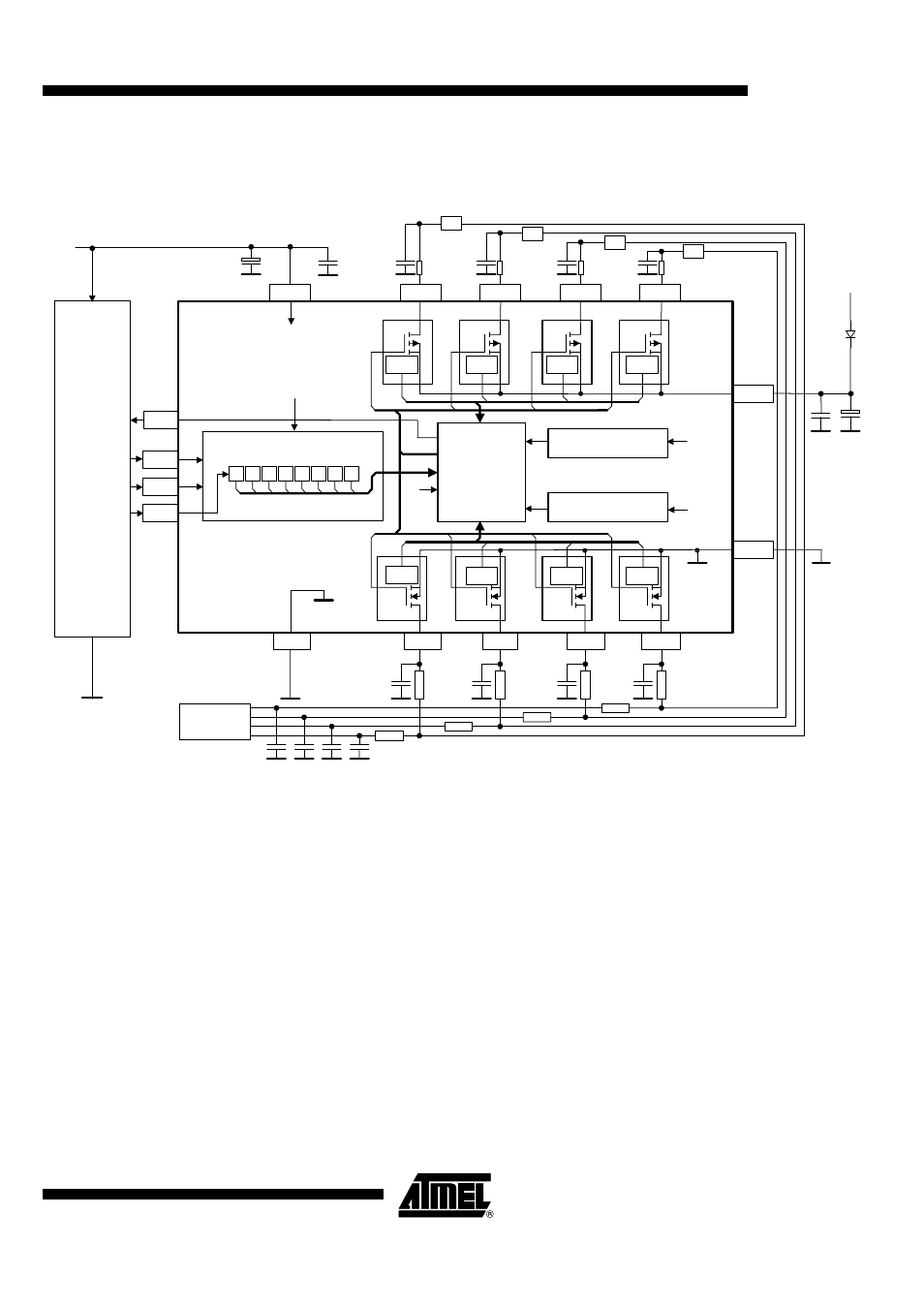
Figure 5. Application Circuit
Note:
It is strongly recommended to connect the blocking capacitors at V
S
and V
CC
as close as possible to the power supply and GND
pins. Recommended value for V
S
is less than 100 µF electrolytic in parallel with 100 nF ceramic. Value for electrolytic capacitor
depends on external loads, noise and surge immunity efforts. Recommended value for V
CC
is 33 µF electrolytic in parallel with
100 nF ceramic. The 4-
Ω
resistors connected to the Pins HS1 - HS4 support the protection in case of a short circuit of these
pins to V
Batt
.
LS2
LS3
LS4
STATUS
R *
R *
R *
R *
R * = ca. 4 Ohm (I Lim for inv. supply)
µC
4.7nF
Typical application with
4 Hall-ICs for rotational speed detection
27k
27k
27k
4.7nF
4.7nF
4.7nF
4.7nF
10
0
4.7nF
10
0
4.7nF
10
0
4.7nF
10
0
33µF
V
BATT
100nF
V
CC
100nF
5 V
12 V
27k
Sensor
control
+
47µF
+
V
CC
CLK
DI
CS
HS4
HS3
HS2
HS1
Thermal protection
U6820BM
6
9
8
1
Control
logic
16
3
Power-on reset
V
CC
V
CC
2
7
10
15
5
V
CC
V
CC
4
14
11
13
12
LS1
GND
CC
H
H
3
S
S
4
S
2
S
1
L
S
3
L
S
4
L
S
2
L
S
1
Input register
H
H
&XUUHQW
OLPLWHU
&XUUHQW
OLPLWHU
&XUUHQW
OLPLWHU
&XUUHQW
OLPLWHU
&XUUHQW
OLPLWHU
&XUUHQW
OLPLWHU
&XUUHQW
OLPLWHU
&XUUHQW
OLPLWHU
GND
S
V
S
RR
LR
RF
LF