Rainbow Electronics MAX7491 User Manual
Page 12
MAX7490/MAX7491
Dual Universal Switched-Capacitor Filters
12
______________________________________________________________________________________
Mode 2 Design Equations
Mode 2N
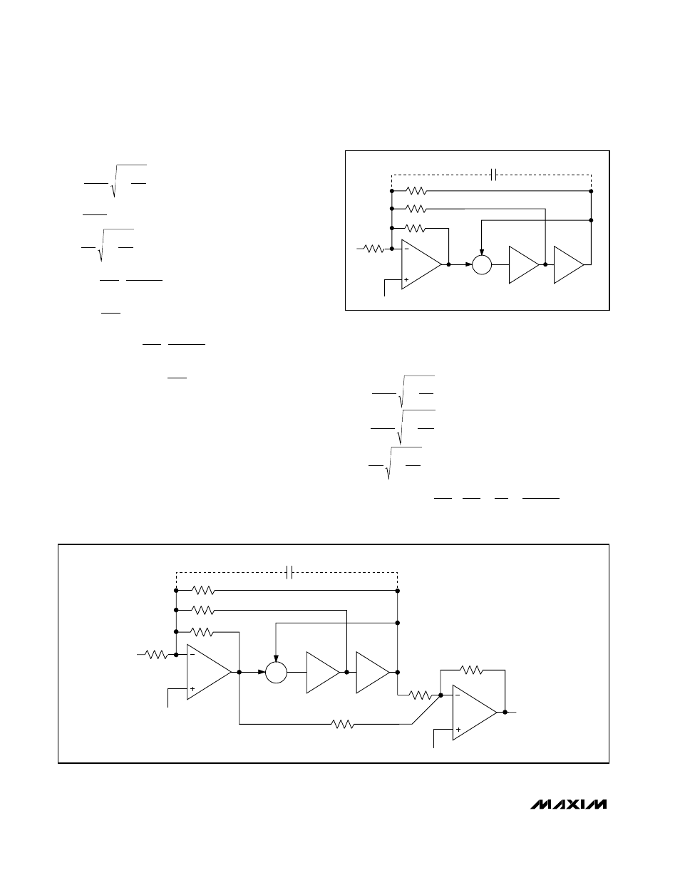
Figure 5 shows the configuration of Mode 2N. This
mode extends the topology of Mode 3A to Mode 2,
where the highpass and lowpass outputs are summed
through two external resistors, R
H
and R
L
, to create a
lowpass notch filter that has higher frequency than the
one in Mode 2. Mode 2 is most useful in lowpass elliptic
designs. When cascading the sections of the
MAX7490/MAX7491, the highpass and lowpass outputs
can be summed directly into the inverting input of the
next section. Only one external op amp is needed.
Mode 2N Design Equations
f
f
R
R
f
f
R
R
Q
R
R
R
R
H
f
Hz
R
R
R
R
R
R
R
R
R
O
CLK
n
CLK
H
L
ON
G
H
G
L
=
+
=
+
=
+
→
=
+
+
100
1
2
4
100
1
3
2
1
2
4
0
2
1
4
4
2
1
(
)
f
f
R
R
f
f
Q
R
R
R
R
H
R
R
R
R
R
H
R
R
H
f
Hz
R
R
R
R
R
H
at f
f
R
O
CLK
n
CLK
OLP
OBP
ON
ON
CLK
=
+
=
=
+
=
+
=
→
=
+
=
=
−
−
−
−
100
1
2
4
100
3
2
1
2
4
2
1
4
4
2
3
1
0
2
1
4
4
2
2
2
1
2
(
)
(
/ )
Σ
∫
∫
LP
BP
S
HP/N
R3
R4
R2
R1
V
IN
C
C
COM
COM
LOWPASS
NOTCH
OUTPUT
+
-
R
H
R
L
R
G
Figure 5. Mode 2N, 2nd-Order Filter Providing a Lowpass Notch Output
Σ
∫
∫
LP
BP
S
HP/N
R3
R4
R2
R1
VIN
C
C
COM
+
-
Figure 4. Mode 2, 2nd-Order Filter Providing a Highpass
Notch, Bandpass, and Lowpass Outputs