Table 1. filter operating modes, Table 2. definition of terms – Rainbow Electronics MAX7491 User Manual
Page 10
MAX7490/MAX7491
Dual Universal Switched-Capacitor Filters
10
______________________________________________________________________________________
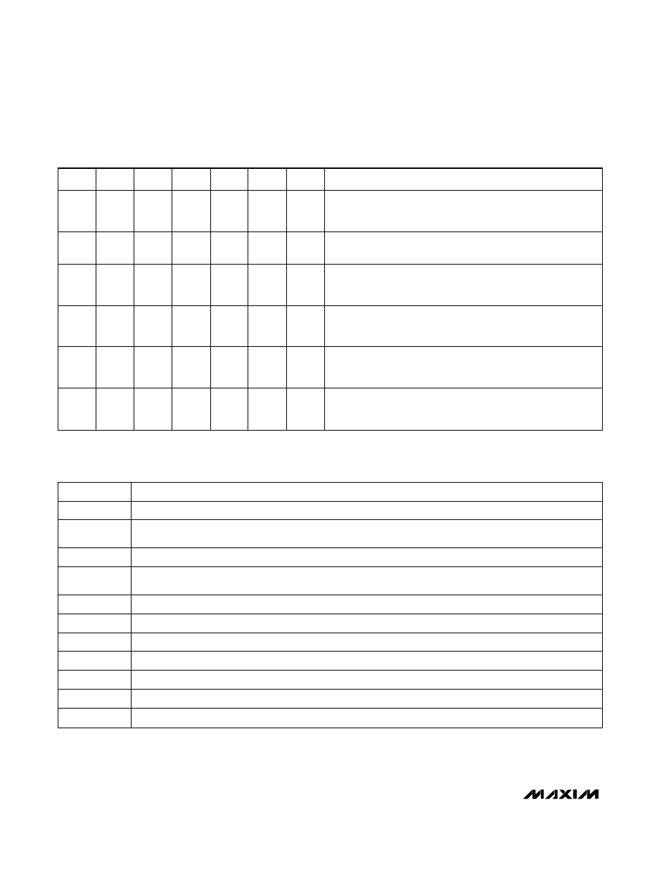
Table 1. Filter Operating Modes
MODE
LP
HP
BP
N
L P- N *
H P- N *
COMMENTS
1
•
•
•
f
CLK
/f
O
ratio is the nominal value. Good for bandpass filters
with identical sections cascaded, higher order Butterworth filters,
high-Q bandpass, low-Q notches.
1B
•
•
•
Same as Mode 1 with f
CLK
/f
O
ratios greater than the nominal
value.
2
•
•
•
Combination of Mode 1 and Mode 3; f
CLK
/f
O
ratios always
less than the nominal value. Less sensitivity to resistor tolerances
than Mode 3.
2N
•
Extension of Mode 2 that allows higher frequencies. Highpass
and lowpass outputs are summed with external op amp and
two resistors. Good for lowpass elliptic filters.
3
•
•
•
Adjustable f
O
above and below the nominal frequency.
Commonly used for multiple-pole Chebyshev filters, all-pole
higher order bandpass, lowpass, and highpass filters.
3A
•
•
•
•
•
Extension of Mode 3 that needs an external op amp and
two additional resistors. Commonly used for lowpass or higher
elliptic or Cauer filters.
* LP-N = lowpass notch, HP-N = highpass notch. Both require an external op amp. See Definition of Terms (Table 2).
Table 2. Definition of Terms
TERM
DEFINITION
f
CLK
The clock frequency applied to the switched-capacitor filter.
f
O
The center frequency of the 2nd-order complex pole pair, f
O
, is determined by measuring the peak response
frequency at the bandpass output.
f
NOTCH
The frequency of minimum amplitude response at the notch output.
Q
Quality factor, or Q, is the ratio of f
O
to the -3dB bandwidth of the 2nd-order bandpass filter. Q also determines
the amount of amplitude peaking at the lowpass and highpass outputs, but is not measured at these outputs.
H
OBP
The gain in V/V of the bandpass output at f = f
O
.
H
OLP
The gain in V/V of the lowpass output at f
→0Hz.
H
OHP
The gain in V/V of the highpass output at f
→f
CLK
/2.
H
ON1
The notch output gain as f
→0Hz.
H
ON2
The notch output gain at f = f
CLK
/2.
LP-N
A notch output with H
ON1
> H
ON2.
HP-N
A notch output with H
ON1
< H
ON2.