Rainbow Electronics MAX7491 User Manual
Page 11
MAX7490/MAX7491
Dual Universal Switched-Capacitor Filters
______________________________________________________________________________________
11
have to track Q). The notch and bandpass center fre-
quencies are identical. The notch output gain is the
same above and below the notch center frequency.
Mode 1 can also be used to make high-order Butter-
worth lowpass filters, low Q notches, and multiple-order
bandpass filters obtained by cascading identical
switched-capacitor sections.
Mode 1 Design Equations
Mode 1B
Figure 3 shows the configuration of Mode 1B. R5 and
R6 are added to lower the feedback voltage from the
lowpass output to the summing input. This allows the
clock-to-center frequency to be adjusted beyond the
nominal value. This mode essentially has the same
functions and speed as Mode 1 while providing a high-
Q with f
CLK
/f
O
ratios greater than the nominal value.
Mode 1B Design Equations
Mode 2
Figure 4 shows the configuration of Mode 2. Mode 2 is
a combination of Mode 1 and Mode 3. In this mode,
f
CLK
/f
O
is always less than the part’s nominal ratio.
However, it provides less sensitivity to resistor toler-
ances than does Mode 3. It has a highpass notch out-
put where the notch frequency depends solely on the
clock frequency.
f
f
R
R
R
f
f
Q
R
R
R
R
R
H
R
R
R
R
R
H
R
R
H
as f
Hz
R
R
H
at f
f
R
R
O
CLK
n
O
OLP
OBP
ON
ON
CLK
=
+
=
=
+
=
+
=
→
=
=
=
−
−
−
−
100
6
6
5
3
2
6
6
5
2
1
6
5
6
3
1
0
2
1
2
2
1
1
2
(
)
(
/ )
f
f
f
f
Q
R
R
H
R
R
H
R
R
H
as f
Hz
R
R
H
at f
f
R
R
O
CLK
notch
O
OLP
OBP
ON
ON
CLK
=
=
=
=
=
→
=
=
=
−
−
−
−
100
3
2
2
1
3
1
0
2
1
2
2
1
1
2
(
)
(
/ )
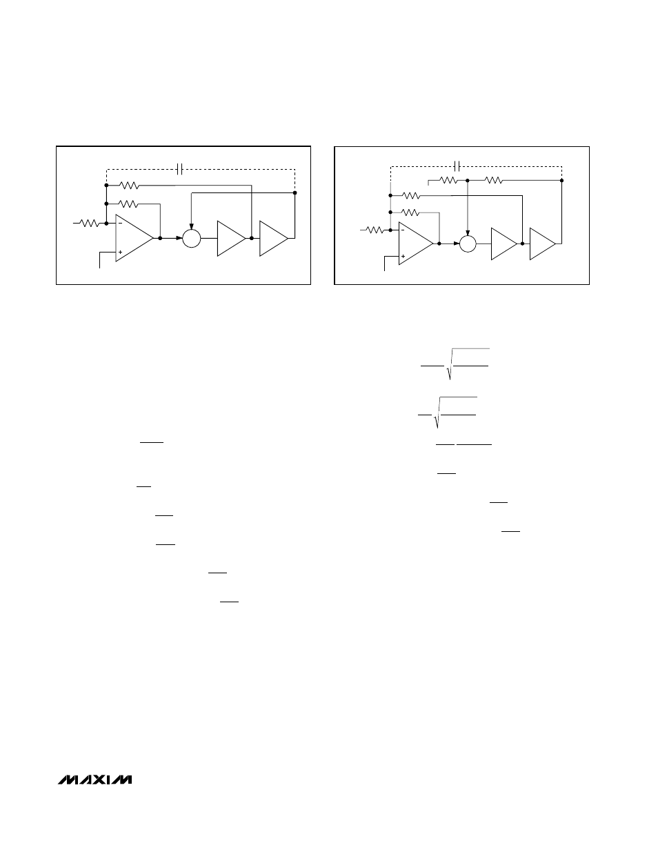
Σ
∫
∫
LP
BP
S
N
R3
R2
R1
V
IN
C
C
COM
+
-
Figure 2. Mode 1, 2nd-Order Filter Providing Notch, Bandpass,
and Lowpass Outputs
Σ
∫
∫
LP
BP
S
N
R3
R6
R5
R2
R1
V
IN
C
C
COM
COM
+
-
Figure 3. Mode 1B, 2nd-Order Filter Providing Notch, Bandpass,
and Lowpass Outputs