Installing the 9216-oe-dm – Cobalt Digital COMPASS 9216-OE-DM AES_EBU Fiber Audio De-Embedder User Manual
Page 18
2-4
••••
Installation
9216-OE-DM User Manual
••••
(V 1.1)
Installing the 9216-OE-DM
The 9216-OE-DM uses a single mode, LC/UPC connector to interface with the RM20-9216-B Full
Rear Module. This section outlines how to install the 9216-OE-DM in a 20-slot frame.
Use the following procedure to install the 9216-OE-DM in a 20-slot frame:
1.
Locate the Rear Module you installed in the procedure “Installing a Rear Module”.
2.
Ensure that the Rear Module the RM20-9216-B Full Rear Module.
3.
Remove the dust caps from the connector on the card end.
•
Refer to Figure 2.1 and Figure 2.3 for dust cap locations.
•
Refer to the section “Important Laser Safety Measures and Notices” at the
beginning of this manual for safety information when handling fiber optic
components.
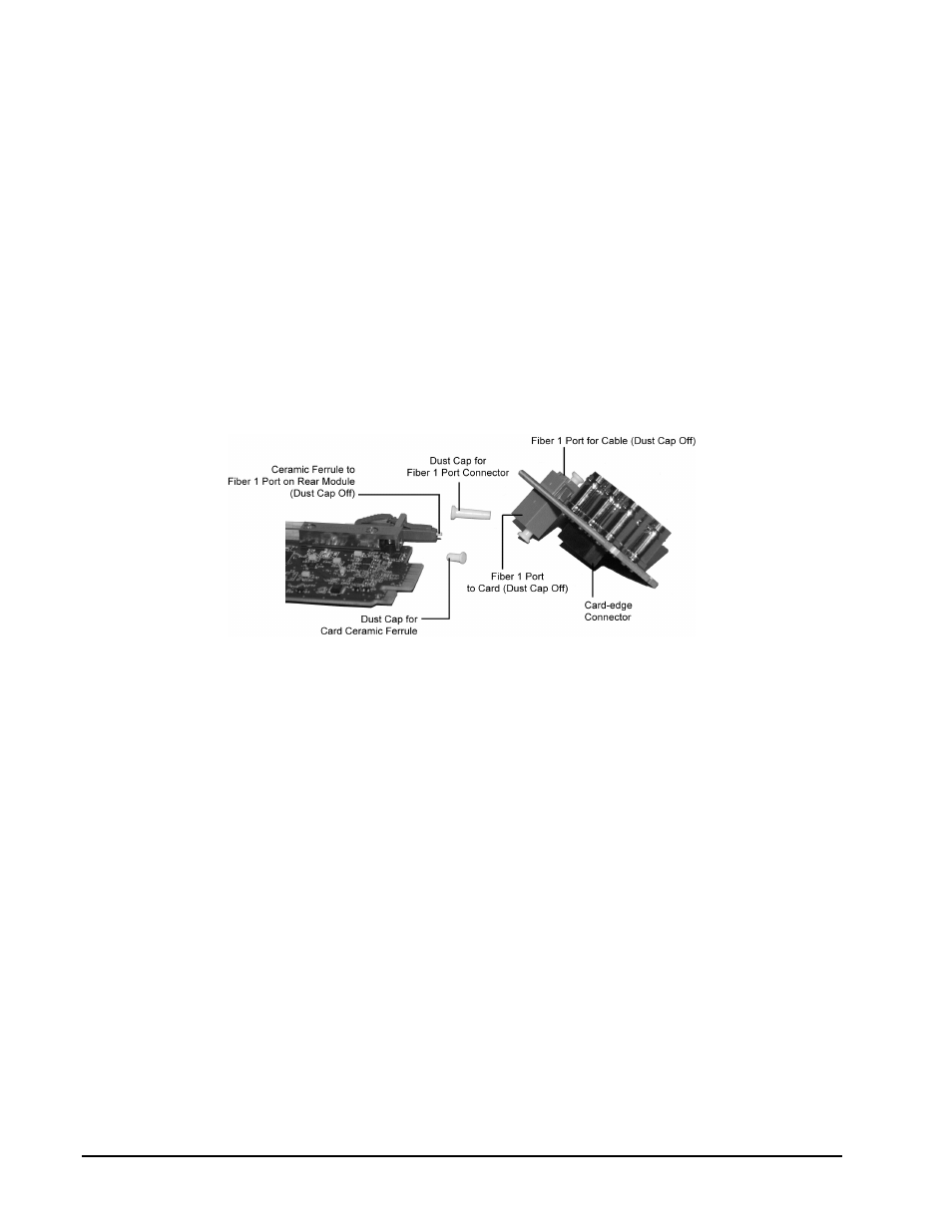
Figure 2.3 Card Connectors with Dust Caps Removed
4.
Ensure that the exposed surface of the ceramic ferrule of the connectors is clean. Refer to
the section “Working with Fiber Optic Connectors” for cleaning tips.
5.
Hold the card by the edges and carefully align the card-edges with the slots in the frame.
6.
Fully insert the card into the frame until the rear connection plus is properly seated in the
Rear Module. You will feel a click when the card mates onto the rear module.
7.
Affix the supplied Rear Module Label to the BNC area of the Rear Module.
8.
Remove the dust cap from the Fiber 1 port (the topmost fiber optic port) on the Rear
Module that faces the exterior of the frame.
9.
Ensure the ceramic ferrule of the Fiber 1 port connector is clean..
10.
Cable your rear module as outlined in the section “Cabling for the 9216-OE-DM”.
This completes the procedure for installing the 9216-OE-DM in a 20-slot frame.