Daystar KG09107 User Manual
Page 3
5
1. Place the vehicle on a level surface. Prior to beginning,
record ride height on each side of the vehicle by measur-
ing from the center of the spindle to a consistent point on
the wheel well. Record these measurements for future
reference.
2. Put the transmission in Park or 1
st
gear (manual trans-
missions) and chock the rear tires and set parking brake.
3. Raise the front of the vehicle using a jack. Raise it
enough to completely unload the front suspension. Place
a jack stand under each frame rail just behind the lower
control arms for the front suspension. Ease the frame
down on to the stands, but leave a slight load on the jack
as a safety precaution.
4. Verify the front tires are off the ground and that the sus-
pension is unloaded, or at full extension travel.
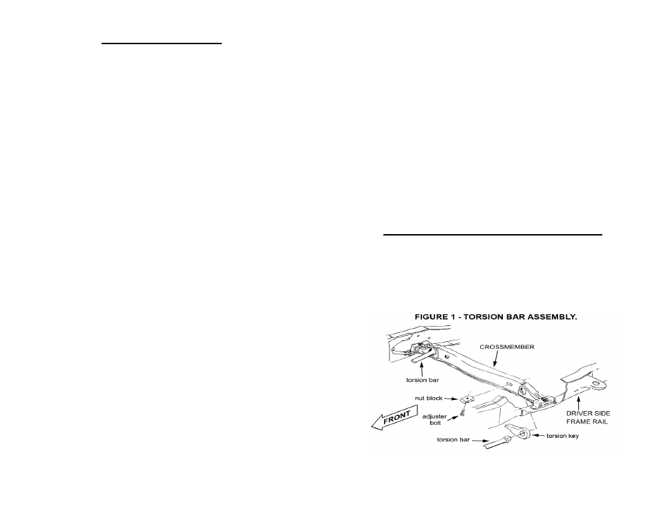
5. Locate the torsion bar crossmember. There is a bolt on
each side of the crossmember that adjusts torsion bar
preload. Measure or mark the exposed length of the ad-
juster bolt for reference during re-assembly. See Figure
1.
6. Position the appropriate torsion bar puller tool on the
crossmember. Be sure the top of the puller tool engages
the recess present in most crossmembers. Also be sure
the lower end of the puller tool engages a recess on the
torsion key near the adjuster bolt. See Figure 2.
Installation Instructions
6
NOTE: Various types of puller tools are available, however, due to the
extreme loads present in four-wheel drive suspension systems, we have
found the two-jaw style tool that clamps to the crossmember tends to slip
and damage the crossmember. A C-clamp style puller tool is preferred and
7. Locate the torsion bar crossmember. There is a
bolt on each side of the crossmember that adjusts
torsion bar preload. Measure or mark the ex-
posed length of the adjuster bolt for reference
during re-assembly. See Figure 1.
8. Position the appropriate torsion bar puller tool on
the crossmember. Be sure the top of the puller
tool engages the recess present in most cross-
members. Also be sure the lower end of the pull-
er tool engages a recess on the torsion key near
the adjuster bolt. See Figure 2.
Use only approved tools for this installation