Electronics 590 User Manual
Page 3
3
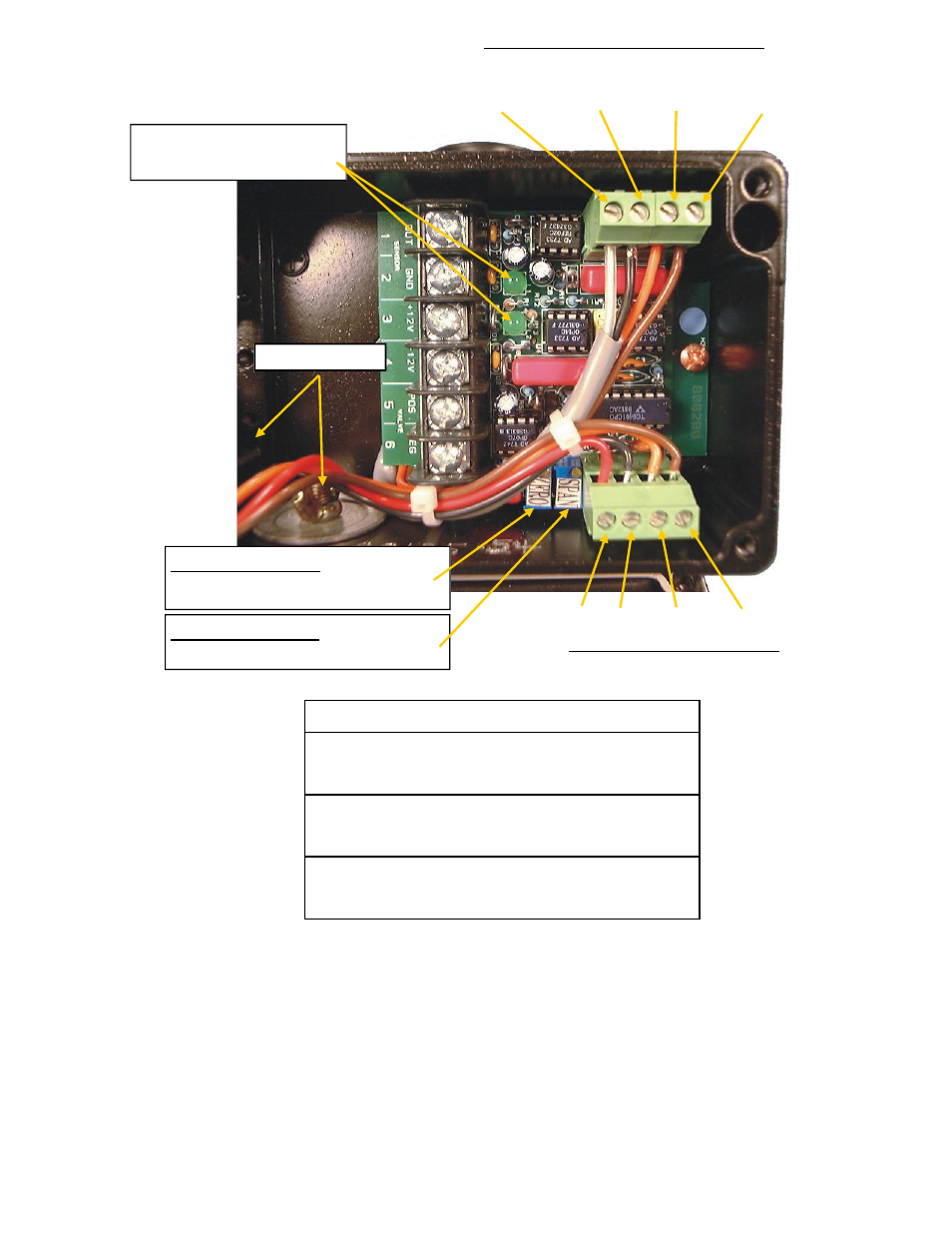
Factory MagnaValve Connections
Sensor wires
Power Coils
White (clear) Black
Orange
Brown
Two LED’s indicate the
presence of ±12Vdc.
Conduit Ports
Red Black Orange Brown
Valve Driver Connections
SPAN Adjustment – Used to cali-
brate the maximum flow
ZERO Adjustment – Used to set
0 Volts for a no flow condition
Pair 1
White
1. 0-5VDC out
Black
2. 0VDC
Pair 2
Green
3. +12VDC
Black
4. –12VDC
Pair 3
Red
5. (+) MagnaValve
Black
6. (-) MagnaValve
Typical Customer wiring connections
Notes:
1. The Magna valve is calibrated at the factory. A catch and weigh test is recommended during
installation. Make any adjustments for maximum flow using the Span at the Magnavalve only.
2. All cable shields at the valve must be isolated from any part of the valve and machine. The
shields should be terminated at the controller only.
3. A separate conduit for MagnaValve cables must be used to prevent and interference from oth-
er equipment. Multiple MagnaValve cables may be routed in the same conduit.