Ac-24 controller cable connection, Remote valve driver cable connection – Electronics WM 3000-24 User Manual
Page 8
8
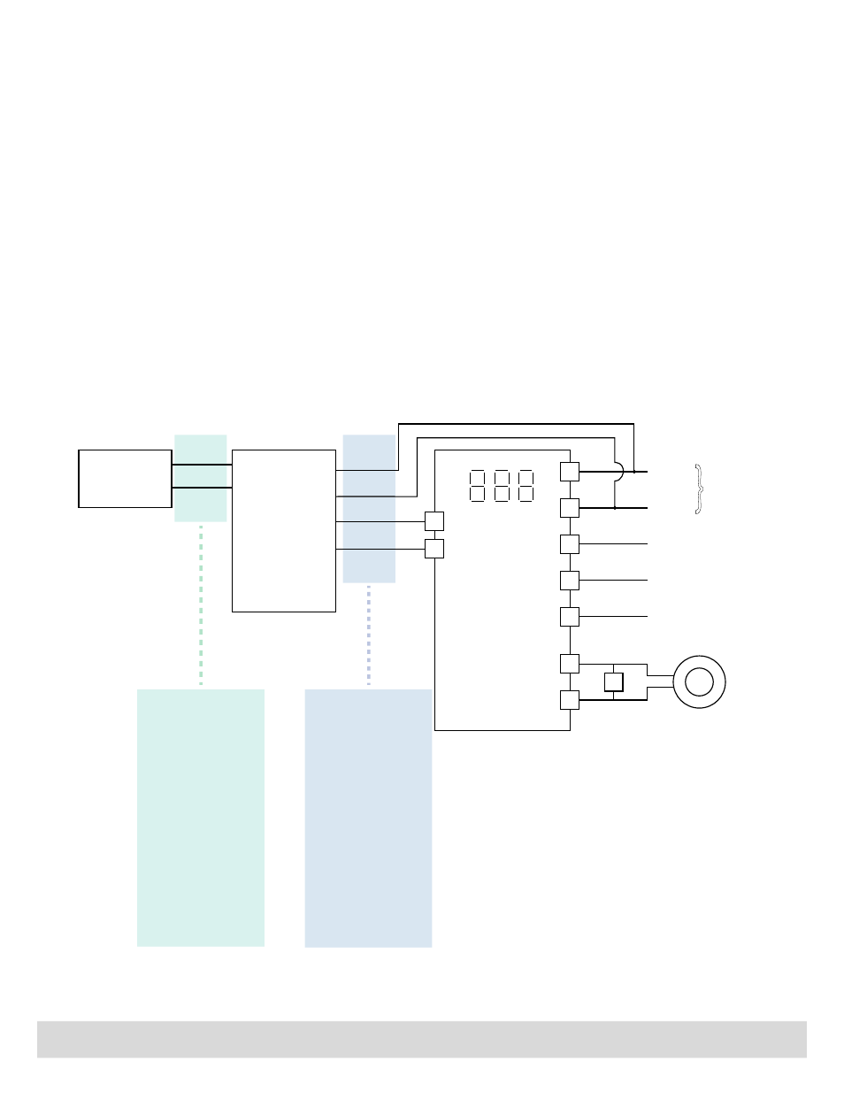
AC-24 Controller Cable Connection
Locate valve within
3 ft/1 m of wheel
feedspout media inlet
Cable #1
White
Green
24 Vdc
0 Vdc
Enable Input
Enable Output
Flow Command
Input
Flow Command
Output
}
Blue
Orange
Cable #2
Red
Black
Valve driver module
located in customer
electrical control panel
24 Vdc
0 Vdc
Customer
Power
Supply
Shunt
0.05 Ω
Remote Setpoint
(if used)
Recorder output
(if used)
Remote Enable
(if used)
100:5 Current Transformer
Pass one loop through
center 0-100 Amps
current transformer.
0-100 Amps Input
0-5 Amps Output
Cable #1- Wiring from
the MagnaValve to the
Remote Valve Driver
should be in a private
conduit (no adjacent
motor leads, etc).
Use 18AWG or larger
wire size for runs over
30 ft (10 m). A six-foot
cable and plug are
supplied with the
MagnaValve and only
the green and white
wires need to be
connected. Ignore the
other wires in the cable.
4
8
11
19
2
18
9
5
7
WM 3000-24
REMOTE
VALVE DRIVER
AC-24 CONTROLLER
Cable #2 - Use only
four wires in Cable #2:
Connect the Red and
Black wires to 24 Vdc
power and the Blue
and Orange wires to
AC-24 Controller.
Do not use White or
Green wires in this
cable.
Remote Valve Driver Cable Connection
The Remote Valve Driver should be installed in customer’s electrical panel. The 6-pin plug and cable wires connect
to customer’s wiring per the following:
Black
Customer Power Supply in control panel - Power bus common 0 Vdc
Red
Customer Power Supply in control panel - Power bus hot +24 Vdc
Blue
24 Vdc Enable Input - connect to AC-24 Controller Screw terminal #9, Enable Output
Orange 0-10 Vdc Flow Command Input - connect to AC-24 Controller Screw terminal #8, Flow Command Output
Green MagnaValve power signal - connect to valve driver, Green only
White MagnaValve power signal - connect to valve driver, White only