Из й, Operation – Electronics WM 3000-24 User Manual
Page 5
5
и
з
й
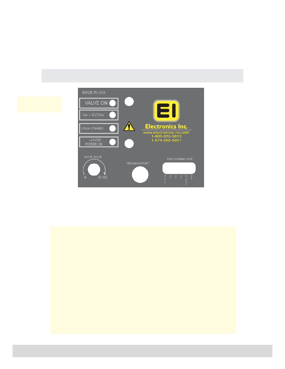
Valve Pulse
Rate at which the valve dispenses shot. The Valve Pulse
is factory set to match the best flow characteristics of
the media (cast steel or cut wire). The typical operation
rate is 8 Hertz.
Test Connector
Provides access to
diagnostic voltages.
• 0 - 10 Vdc input
• 24 Vdc “Enable” input
• 6 - 20 Hertz pulse rate
• 0 Vdc common
Operation
Remote Valve Driver
Va
lve Driver Panel (behind the cover plate)
*Diagnostic LEDs
Valve On. Indicates when power is being sent to the MagnaValve’s electromagnet. When the
LED is on, the valve is on for full capacity flow rate. When the LED is off, the MagnaValve’s
permanent magnet has stopped the media flow. When the LED is blinking, the shot flow is
being regulated.
Vin > 0.25 Vdc. Indicates that an analog signal input greater than 0.25 Vdc has been received.
When this LED is off, no media flow is allowed. The input signal range is 0 -10 Vdc. At 10 Vdc,
the MagnaValve will open to full capacity. The relationship between the 0 -10 Vdc input signal
and actual flow rate is non-linear.
24 Vdc Enable. Indicates that the 24 Vdc Enable Signal has been received. When the LED is
off, the MagnaValve is inhibited and no shot will flow. This feature is provided as an on-off
action so the 0-10 Vdc input signal does not have to be disabled or removed.
24 Vdc Power. Indicates that 24 Vdc is available to operate the electromagnet for media flow.
It should always be available and able to supply 2 Amps.
All four LEDs must be on in order to have media flow.
Diagnostic LEDs*
The large knurled screw on the front cover of the Remote Valve Driver can be removed to gain
access to the factory adjustments. Please refer all adjustments to qualified personnel.