Scr board setup, Chapter 12 scr board setup – Grain Systems PNEG-1181 User Manual
Page 69
PNEG-1181 Portable Dryer Troubleshooting
69
12. SCR Board Setup
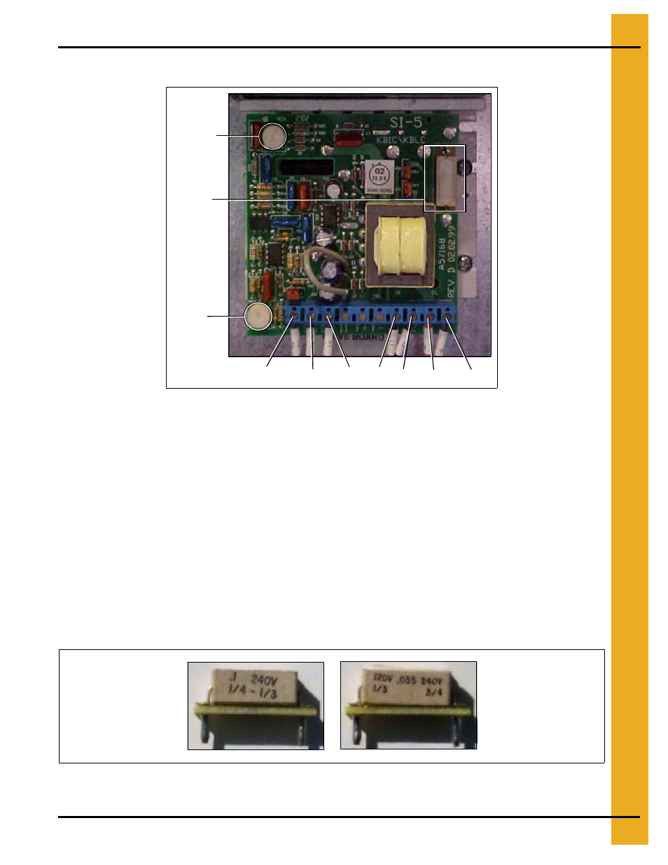
SCR Board Terminals and Min./Max. Adjustment Locations
Figure 12A
* The SCR board is located in the upper control box.
* Terminals L1 and L2 are the input terminals. When the unload system is turned on, there should be
220 volts AC across these terminals.
* Terminals A+ and A- are the output terminals. The voltage across these terminals is DC and will vary
depending on where the speed control potentiometer is set.
* The item circled at the top of the SCR board in
is the minimum set potentiometer. This will
be used in the SCR board set up to set minimum DC voltage.
* The item circled at the bottom of the SCR board in
is the maximum set potentiometer. This
will be used in the SCR board set up to set maximum DC voltage.
IMPORTANT: After the new board has been installed be sure to remove the resistor (
) from the old board and install it in the new board. Simply pull the resistor from the two
pin socket and install in the same socket on the new board.
Figure 12B
A+
A-
L2
L1
+12
SIG
COM
MAX
Resistor
MIN
Resistor for 3/4HP meter
roll motors used on 14 Ft.
dryers and longer.
(Part # D33-001)
Resistor for 1/3HP meter
roll motors used on 12 Ft.
dryers and shorter.
(Part # D03-0039)