Wiring instructions – Grain Systems PNEG-1928 User Manual
Page 5
PNEG-1928
Page 5 of 9
UV Sensor Retrofit Instruction Manual for Portable Dryers
Wiring Instructions
The factory and the UV wirings diagram are included (
will help show the difference between the current and modified versions.
1. Cut the supplied red wire into two (2) equal pieces. Strip the insulation off both ends of each wire.
Attach one wire between terminals 10 and 11. Attach the other wire between terminals 5 and 6.
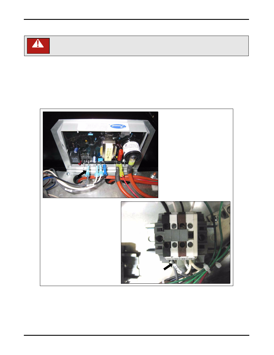
2. Locate the V1 wire on the fenwal board as shown in
. Leave the wire connected to the
fenwal board and follow it to the terminal strip. Disconnect the wire which will be in terminal
number 21 on the terminal strip.
Figure 8 Locating the V1 grey wire on the fenwal board and terminal 21.
3. Re-locate the grey wire to the relay base terminal 11 which will also contain a jumper wire between
terminals 10 and 11.
4. Strip the insulation off both ends of the supplied grey wire. Attach one end of the grey wire to the
terminal number 21 on the terminal strip (where you removed the grey wire above) and attach the
other end to the relay base terminal 9.
Disconnect power and lock out prior to performing this service.
DANGER