Own in – Grain Systems PNEG-1928 User Manual
Page 4
Page 4 of 9
PNEG-1928
UV Sensor Retrofit Instruction Manual for Portable Dryers
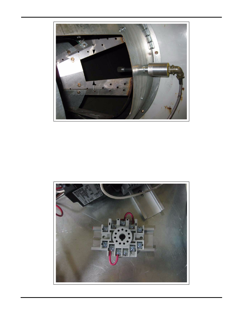
Figure 6 Sensor Location Pointing between Burner Veins
Once UV sensor has been mounted to sight tube then attach the five (5) pin cable to sensor. Route the
cable through the black plastic heyco cord connector (FH-1310) then through either an existing hole in the
fan/heater control box or drill a new 7/8" hole. Try to keep the cable entrance location close to the relay
and fenwal board.
Find a location to mount the 3" aluminum din rail and relay base inside the fan/heater control box.
Drill two (2) 9/64" holes that will be used to mount the din rail to the heater back panel. Use the two (2)
supplied self-tapping phillip screws (S-2786) in the drilled holes to mount the din rail. Once the din rail is
secure snap the relay base to the din rail as shown in
Figure 7 Relay Base
- PNEG-1890 (16 pages)
- PNEG-595 (26 pages)
- PNEG-1472 (30 pages)
- PNEG-897 (58 pages)
- PNEG-838 (4 pages)
- PNEG-1755 (36 pages)
- PNEG-524 (24 pages)
- PNEG-1080 (2 pages)
- PNEG-728 (47 pages)
- PNEG-673 (57 pages)
- PNEG-1717 (88 pages)
- PNEG-823 (42 pages)
- PNEG-630-6S (23 pages)
- PNEG-1876 (80 pages)
- PNEG-102 (2 pages)
- PNEG-366 (51 pages)
- PNEG-1626 (1 page)
- PNEG-1874 (78 pages)
- PNEG-1798 (34 pages)
- PNEG-1927 (4 pages)
- PNEG-924 (2 pages)
- PNEG-582 (26 pages)
- PNEG-012 (46 pages)
- PNEG-1797 (86 pages)
- PNEG-546 (26 pages)
- PNEG-951 (102 pages)
- PNEG-1650 (92 pages)
- PNEG-1649 (50 pages)
- PNEG-1376 (88 pages)
- PNEG-361 (46 pages)
- PNEG-338 (32 pages)
- PNEG-1276 (78 pages)
- PNEG-1283 (22 pages)
- PNEG-1089 (14 pages)
- QSG-001 (2 pages)
- PNEG-950 (96 pages)
- PNEG-1590 (3 pages)
- PNEG-501 (33 pages)
- PNEG-1447 (68 pages)
- PNEG-707GSI (446 pages)
- PNEG-349 (32 pages)
- PNEG-236 (22 pages)
- PNEG-743 (16 pages)
- PNEG-900 (54 pages)
- PNEG-1935 (92 pages)