Sight tube assembly instructions, Sensor mounting – Grain Systems PNEG-1928 User Manual
Page 3
PNEG-1928
Page 3 of 9
UV Sensor Retrofit Instruction Manual for Portable Dryers
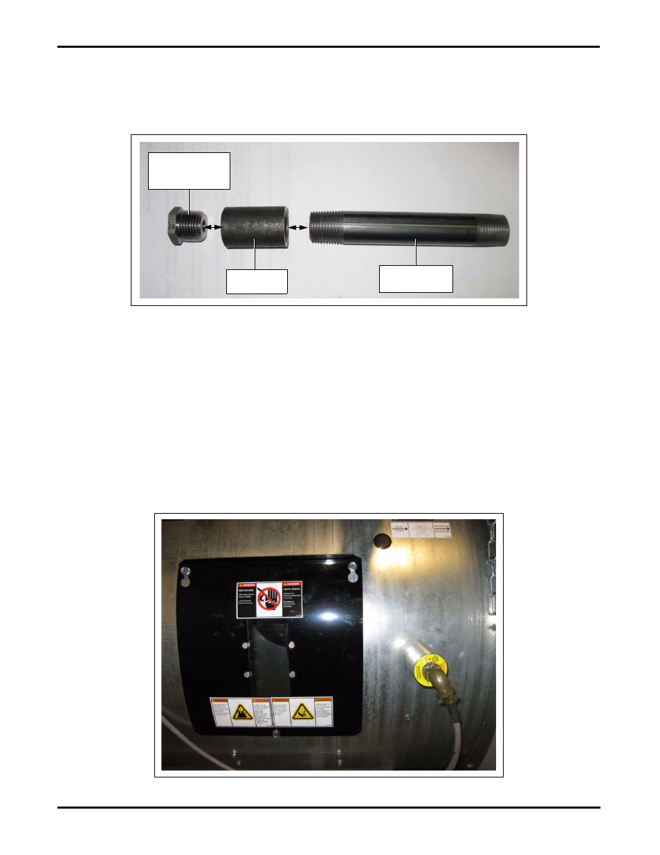
Sight Tube Assembly Instructions
Locate 1/2" x 5" nipple (THH-4129) and attach the 1/2" coupler (D67-0005) to one end of this nipple.
Then attach the 1/2" to 1/8" reducer bushing (007-1149-9) into the 1/2" coupling as shown in
(No sealant is necessary.)
Figure 4 Sight Tube Assembly
Sensor Mounting
The location to mount the sensor is critical in providing reliable flame sense. The sensor needs to
have a constant view to the flame of the burner during all burner modes and operations. Typically the
best location is just to the right of the inspection window plate as shown in
. The sensor tube
needs to be pointing between the burner veins as shown in
. It is best if the
sensor points slightly downward to allow any moisture that may be present to drain away from the
UV sensor component.
Once you have determined the sensors location drill a 7/8" hole into the side of the can and attach the
UV sight tube assembly into the hole using two (2) 1/2" lock nuts included with kit. Be sure to leave plenty
of thread sticking through the burner can to mount the UV sensor.
Figure 5 Outside Sensor Location
1/2" to 1/8"
Reducer bushing
(007-1149-9)
1/2" x 5" Nipple
(THH-4129)
1/2" Coupler
(D67-0005)