Hopper support system layout – Grain Systems Tanks PNEG-603 User Manual
Page 25
6. Hopper Assembly
PNEG-603 4" Commercial Hopper Tank
25
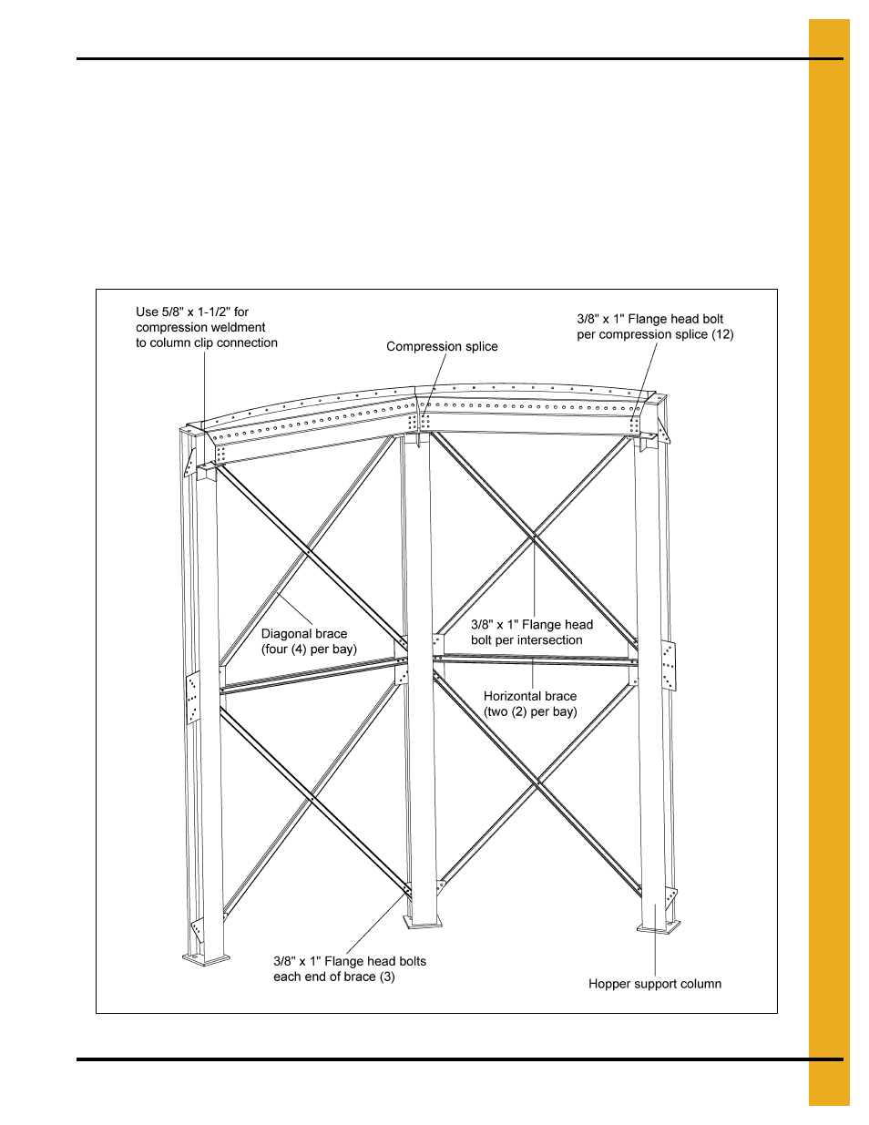
Hopper Support System Layout
Connect hopper support column bracing as depicted
. Use 3/8" x 1" hex flange head bolts for
all bracing connections. The horizontal brace consist of two (2) formed channels placed back to back.
Connect diagonal braces at their intersection with one 3/8" x 1" hex flange head bolt. The compression
elements can be placed on the top of the column while the bracing is being installed. To ease construction
pre-install a compression splice on the end of each compression element (3/8" x 1" hex flange head bolts).
Compression elements are connected to column supports clips with a 5/8" x 1-1/2" hex bolt at each end.
The compression element can be connected to column top plate at this time for alignment, however this
bolt will have to be removed before the tank is set on the hopper support structure. Connect adjacent
compression elements with compression splices.
Figure 6B
- Bin Accessories PNEG-1883 (26 pages)
- Bin Accessories PNEG-104 (2 pages)
- Bin Accessories PNEG-1859 (90 pages)
- Tanks PNEG-4075 (168 pages)
- Bin Accessories PNEG-1789 (7 pages)
- Special Roofs PNEG-1845 (28 pages)
- Unload Augers PNEG-1550 (22 pages)
- Bucket Elevtors, Conveyors, Series II Sweeps PNEG-1842 (114 pages)
- Tanks PNEG-1784 (5 pages)
- Bin Accessories PNEG-1336D (34 pages)
- Bucket Elevtors, Conveyors, Series II Sweeps PNEG-1618 (10 pages)
- Tanks PNEG-4072G (162 pages)
- Unload Augers PNEG-1556 (58 pages)
- Bin Accessories PNEG-268 (2 pages)
- Bin Flooring PNEG-1830 (44 pages)
- Bin Flooring PNEG-1835 (48 pages)
- Bin Flooring PNEG-1816 (42 pages)
- Bin Accessories PNEG-1870 (28 pages)
- Bin Accessories PNEG-1088 (30 pages)
- Tanks PNEG-1880 (30 pages)
- Tanks PNEG-4054G (168 pages)
- Unload Augers PNEG-1583 (28 pages)
- Bin Accessories PNEG-318 (180 pages)
- Bucket Elevtors, Conveyors, Series II Sweeps PNEG-970 (36 pages)
- Bin Flooring PNEG-219 (32 pages)
- Tanks PNEG-083 (28 pages)
- Bin Flooring PNEG-1826 (42 pages)
- Bin Accessories PNEG-1802 (50 pages)
- Unload Augers PNEG-1521 (64 pages)
- Tanks PNEG-4090A (166 pages)
- Bin Accessories PNEG-1933 (2 pages)
- Bin Accessories PNEG-1496 (2 pages)
- Bucket Elevtors, Conveyors, Series II Sweeps PNEG-1902 (7 pages)
- Bin Accessories PNEG-1177 (16 pages)
- Bucket Elevtors, Conveyors, Series II Sweeps PNEG-1204 (59 pages)
- Bin Accessories PNEG-130 (2 pages)
- Bin Accessories PNEG-1451 (102 pages)
- Tanks PNEG-1095 (76 pages)
- Bin Accessories PNEG-1868 (26 pages)
- Bin Accessories PNEG-1840 (32 pages)
- Unload Augers PNEG-790 (18 pages)
- Tanks PNEG-1461 (124 pages)
- Bin Accessories PNEG-1884 (26 pages)
- Bin Accessories PNEG-1852 (26 pages)