Banks Power Dodge Trucks: (Diesel ’03 - 07 5.9L Cummins) Speed Control- Banks Exhaust Brake '03-early 04 User Manual
Page 20
20 |
9 7 0 5 3 v . 8 . 0
housing. torque the V-band
clamp to 12 ft-lbs.
75.
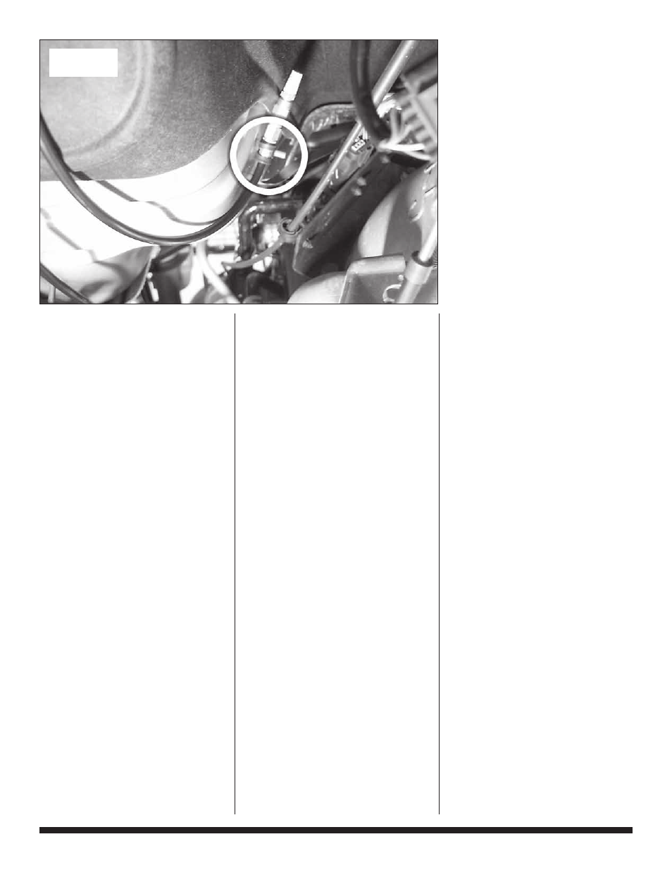
Position and torque the
previously installed exhaust clamp
(in Step 68) to 35 ft-lbs as shown
in Figure 20.
76.
Banks Brake housing is
installed and skip to Step 82.
Stock Exhaust
system with or
without Catalytic
Converter
77.
remove the original turbine
outlet pipe (tOP) by removing the
V-band attaching it to the turbine
housing outlet along with the
clamp attaching it to the catalytic
converter or the intermediate pipe.
It may be necessary to heat the
lower end of the pipe with a torch
to loosen the joint to allow the
pipe to be removed.
78.
Ensure that the surface
of the new supplied turbine
outlet pipe is clean and free of
oil, grease, and dirt. Clean and
dry as required using a cloth
dampened with rubbing alcohol
or similar cleaning solution. Peel
the protective backing off of the
adhesive tape on the supplied
turbine exhaust gasket. Firmly
press it against the side of Banks
turbine outlet pipe that mates to
the turbine housing for at least 60
seconds.
79.
attach the smaller supplied
V-band clamp to the turbine
flange on the vehicle. Install the
Banks tOP in the V-band clamp
on the turbine housing side. snug
the clamp and ensure that the pipe
is centered on the V-band flange
on the turbine housing. Loosely
tighten the V-band.
80.
slide the provided 3
1
⁄
2
”
clamp onto the catalytic converter
or the intermediate pipe and install
the supplied outlet pipe. Loosely
clamp them together.
81.
Install Banks Brake assembly
between the tOP and the outlet
pipe. the actuator on the brake
shall be oriented closer to the
transmission. see Figure 19.
Place the supplied exhaust
flange gasket between the brake
assembly and the 4-bolt exhaust
flange. use the supplied four
(4) sets of the
7
⁄
16
” x 1
1
⁄
2
” bolts,
washers and nuts to mount the
housing to the turbine down pipe.
snug the nuts up and adjust the
brake housing to align the two
flange halves with each other.
Loosely tighten the bolts.
82.
Engage the exhaust brake
outlet pipe in the larger supplied
V-band clamp. snug the clamp
and ensure that the outlet pipe is
centered on the V-band flange on
the brake housing. Loosely tighten
the V-band.
83.
With everything positioned
properly, begin to tighten the
clamps starting with the ones
closest to the turbo and working
your way back. torque the
V-band clamp on the turbine
housing outlet to 80 in-lbs (not
ft-lbs). torque the
7
⁄
16
” hardware
to 48 ft-lbs.
84.
Position and torque the
previously installed exhaust clamp
in Step 76 to 35 ft-lbs as shown
in Figure 20.
85.
Banks brake housing is
installed. Proceed to Step 82.
86.
route the pneumatic hose
from the compressor panel outlet
along the driver’s side frame rail
toward the back of the vehicle.
see Figure 22. use cable ties as
indicated.
87.
route the air hose across
and over the transmission
following the plastic body
Figure 24