Banks Power Dodge Trucks: (Diesel ’03 - 07 5.9L Cummins) Speed Control- Banks Exhaust Brake '03-early 04 User Manual
Page 14
14 |
9 7 0 5 3 v . 8 . 0
along the fender with the factory
harness. they should come around
between the battery and the fuse
box toward the engine block. See
Figure 5. Install a spade on the
BLuE wire.
For APP sensor mounted on the
engine proceed to step 33.
For APP sensor located beneath
the fuse box above the tire
proceed to step 34.
33.
remove and keep the three
(3) bolts that mount the accelerator
pedal position (aPP) sensor to the
engine. turn the aPP sensor to
its side and locate the BrOWN
wire with WhItE stripe on the
electrical connector. Install a t-tap
and plug the Banks Brake BLuE
wire into it. refer to
Figure 6.
re-install the aPP sensor with the
three bolts. Proceed to Step 35.
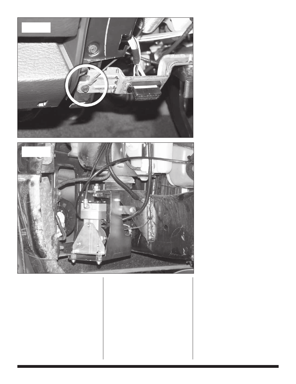
34.
route the BLuE wire toward
the bottom of the fuse box. The
accelerator pedal position (aPP)
sensor is located beneath the
fuse box above the tire. Locate
the BrOWN wire with WhItE
stripe on the wire loom going into
the aPP sensor. Install a t-tap
into this wire and plug the BLuE
Banks wire into it. see Figure 7.
Proceed to Step 35.
35.
On the front of the
engine, find the engine coolant
temperature sensor. Install a
t-tap on the taN wire with
BLaCk stripe or the VIOLEt
wire with OraNGE stripe. route
the Gray Banks Brake wire
underneath the aPP sensor toward
the t-tap and plug in. secure the
wire on the factory harness with a
supplied cable tie.
see Figure 10.
36.
route the GrEEN and
BLaCk wire pair on the Banks
Brake wire harness behind the
battery box along the fender down
toward the back of the bumper
on the driver side. this is the
approximate location where the
compressor panel will be installed.
see Figure 11. secure the wire
along the way with cable ties.
CautION: Do not use force
when working on plastic parts.
Permanent damage to the part
might result.
37.
the Banks Brake switch
will be installed on the driver’s
side of the instrument panel (IP)
next to the steering column. See
Figure 12. remove the headlamp
Figure 14
Figure 15