Banks Power Chevy_GMC Trucks: Duramax LB7 (Diesel ’01 - 04 6.6L) Power Systems- PowerPack & Stinger Systems w_ EconoMind (LB7 & LLY) '01-05 (iQ) Compatible with Optional Banks iQ User Manual
Page 27
96814 v.2.0
27
Section 7 not needed if Banks iQ
will be installed. Please proceed to
Section 8.
CAuTIoN: Do not use force
when working on plastic parts.
Permanent damage to the part
might result.
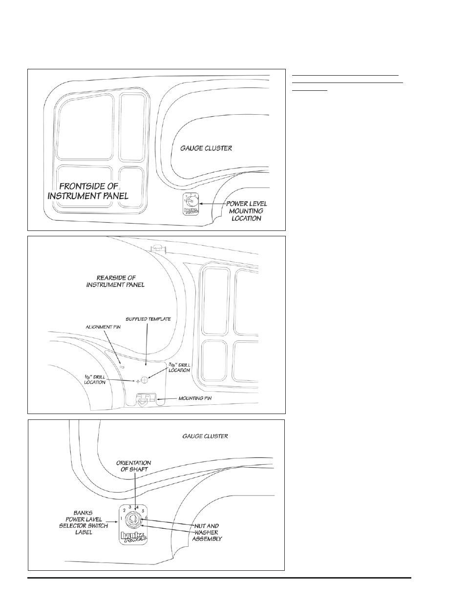
1.
The Power Level Selector switch
will be installed on the driver’s side
of the instrument panel (IP) next to
the steering column (see Figure
44). Carefully remove the IP from
the dashboard by slowly pulling
outwards from the dashboard
around the edges of the IP, allowing
the mounting pins to pull free from
their dashboard sockets. Automatic
transmission equipped vehicles will
need to set the parking brake and
move the shift lever down to the
lowest gear to allow clearance for
instrument panel removal.
2.
Cut out the supplied template
(see
Figure 56 on page 35
) and align
the template onto the rear of the IP,
squarely seating it on the top of the
IP mounting pin (see Figure 45).
3.
Using a
3
⁄
8
” Uni-bit, center the
bit onto the
3
⁄
8
” drill location on the
template and slowly drill through the
IP. Using a
1
⁄
8
” drill bit, center and
drill through the
1
⁄
8
” location on the
template. Remove and discard the
template and any plastic shavings.
4.
On the front side of the IP, align
the Power Level Selector Switch label
onto the previously drilled hole (see
Figure 46).
5.
Remove the nut and internal
tooth washer from the Power Level
Selector Switch. Rotate the shaft
counter clockwise until the shaft
stops. Verify the locating washer tab
is inserted into the #6 position on the
switch (see Figure 47).
NOTE: If the washer is in any position
other then the #6, your EconoMind
Tuner will not select power levels
properly.
6.
After confirming the locating
washer is in the #6 location, install
the switch through the
3
⁄
8
” hole
on the backside of the instrument
panel. The alignment pin should rest
in the
1
⁄
8
” hole and with the switch
fully rotated counter clockwise; the
shaft’s flat side should be facing
the steering column. Secure switch
with internal tooth washer and nut.
Section 7
INSTALLATIoN oF THE PoWER LEVEL SELECToR SWITCH
Figure 45
Figure 44
Figure 46