Banks Power Chevy_GMC Trucks: Duramax LB7 (Diesel ’01 - 04 6.6L) Power Systems- PowerPack & Stinger Systems w_ EconoMind (LB7 & LLY) '01-05 (iQ) Compatible with Optional Banks iQ User Manual
Page 13
96814 v.2.0
13
9.
Remove the bulbs from the turn
signal lamp assembly by turning
the lamp sockets a quarter turn
counterclockwise.
10.
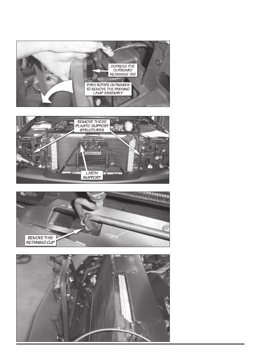
Remove the plastic headlamp
mounting structure on the driver
and passenger side of the vehicle
shown in Figure 12. There are (6)
bolts, (2) torx head bolts, (1) push-
in retainer and (1) large clip that
must be disconnected to remove
the piece from the vehicle, per side.
The plastic piece that resides by
the bumper must be detached from
the headlamp mounting structure,
but will remain on the vehicle. The
retaining clip that attaches the hood
latch cable to the support structure
must also be removed on the driver’s
side.
11.
Remove the four bolts that
secure the upper fan shroud to the
upper radiator cross brace. Remove
the four push-in retainers (2 per side)
that attach the upper section to the
lower section of the fan shroud.
These retainers are removed by
pulling up on the center pin then
prying the entire retainer assembly
out as shown in Figure 9.
12.
Remove the upper section of
the fan shroud from the vehicle. Take
care not to damage the face of the
radiator when removing the shroud.
13.
Remove the two upper
condenser mounting bolts that attach
to the radiator cross brace.
14.
Mark the location of the hood
latch, then remove the hood latch
from the latch support. The latch is
held in place by three bolts. The latch
support is shown in Figure 12. It is
not necessary to remove the cable
from the latch, just place the latch
and cable assembly out of the way.
15.
Remove the two bolts that
attach the latch support to the
radiator cross brace and the 4 lower
attachment bolts (2 per side). The
two bolts that attach the upper
support to the radiator cross brace
are accessed from the engine
compartment side of the vehicle.
16.
Remove the oil-cooler-line
retaining clip as shown in Figure 13.
17.
Swing the latch support forward
as shown in Figure 14.
Figure 11 Parking lamp assembly removal
Figure 12 Removal of headlamp/parking lamp assembly support structures
Figure 13 Oil cooler line retaining clip
Figure 14 Latch support moved out of the way