Banks Power Chevy_GMC Trucks: Duramax LB7 (Diesel ’01 - 04 6.6L) Power Systems- PowerPack & Stinger Systems w_ EconoMind (LB7 & LLY) '01-05 (iQ) Compatible with Optional Banks iQ User Manual
Page 15
96814 v.2.0
15
25.
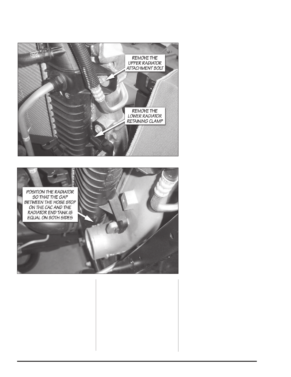
Remove the radiator attachment
bolts and the lower retaining clamps
shown in Figure 18.
26.
Lift the radiator out of it’s
lower saddle mounts and position it
towards the engine so that it is no
longer attached to the charge air
cooler. Take care not to damage the
radiator cooling fins.
27.
Remove the charge air cooler
from the vehicle. Check that the
lower mounting peg grommets
remained in the vehicles frame.
Return them to their home on the
vehicles frame, if they came out with
the charge air cooler.
28.
Remove the metal sleeve from
the upper CAC isolation grommets.
Remove the grommets from the
stock charge air cooler and place
them on the Banks Techni-Cooler.
Reinstall the metal sleeves in the
grommets in the same orientation as
they were removed from the stock
cAc.
29.
Remove the lower radiator
saddle mount grommets from the
stock CAC and install them on the
Banks cAc.
BANkS TECHNICooLER
INSTALATIoN
30.
Place the Banks CAC in the
vehicle. Align the lower CAC
mounting pegs with the rubber
mounts in the vehicle’s frame. There
is a significant amount of play in
the rubber mounts that can allow
them to be aligned with the CAC as
required.
31.
Reinstall the radiator into the
lower saddle mounts of the Banks
cAc.
32.
Reinstall the radiator cross
brace. Leave the attachment bolts
loose to aid in aligning the CAC with
the support.
33.
Install the upper CAC
attachment bolts that were
previously removed. There is enough
play in the lower mounting pads, that
the CAC can be positioned to align
with the upper cross brace. Tighten
the bolts.
34.
Position the radiator so that
it’s centered on the CAC. Check the
gap between the hose stops on the
CAC and the radiator end tanks on
each side of the CAC. Reposition
the radiator relative to the CAC until
the gap is equal on each side. The
location to check is shown in
Figure 19.
35.
Check that the engine cooling
fan can freely spin without contacting
the lower fan shroud. If the fan
contacts the shroud, the shroud must
be realigned with the radiator. The
correct alignment is shown in
Figure 20. Each side of the shroud
should overlap the radiator headers,
and the mounting tabs should fit into
their respective bosses as shown in
Figure 20.
36.
Secure the radiator to the
Banks CAC with the
5
⁄
16
”-18 by 1.0”
long bolts and large OD washers
that were supplied with the Banks
system. Tighten to 10-12 ft-lbs.
37.
Install the lower driver side
radiator-retaining clamp that was
removed from the stock CAC and
secure with the
5
⁄
16
”-18 by 0.5” long
bolts and the smaller OD washers
that were supplied with the Banks
system. Tighten to 10-12 ft-lbs. The
passenger side clamp will contact
the battery support bracket, and is
optional to reinstall.
Figure 18 Radiator attachment bolt and lower clamp
Figure 19 Gap between the CAC hose stop and radiator end tank