Banks Power Chevy_GMC Trucks: Duramax LB7 (Diesel ’01 - 04 6.6L) Power Systems- PowerPack & Stinger Systems w_ EconoMind (LB7 & LLY) '01-05 (PDA) Compatible w_ Optional PowerPDA User Manual
Page 12
20.
Tighten the exhaust clamp at
each of the three (3) joints. Figure
4 illustrates the proper location of
an exhaust clamp on a tubing joint.
Torque the nuts on each of the
exhaust clamps to 35 ft-lb. Note: If a
combination hanger/clamp is utilized,
evenly torque nuts to 35 ft-lb. The
clamps only need to be tight enough
to form a seal and hold the pipes
together. Over tightening the clamps
may cause the system to leak due to
the pipe being crimped. Torque the
four (4) factory flange nuts, previously
removed, to 30 ft-lbs.
21.
Install exhaust tip by sliding
it over the outlet of the tailpipe.
The tip should be positioned so
that the outlet of the exhaust tip
is approximately one (1) inch past
the outlet of the tailpipe or where
aesthetically pleasing.
NOTE: On vehicles with dual rear
wheels, the outlet of the tip should
be placed approximately 3.5 inches
past the outlet of the tailpipe.
Torque the band clamp to 35 ft-lb.
Skip to Step 34 to complete Banks
Monster Exhaust System.
BANkS SPLIT-DuAL MoNSTER
ExHAuST SySTEM (Step 22 thru
33)
22.
Install a 4”saddle clamp onto
the Monster muffler inlet. Install
the Monster muffler inlet onto the
Banks intermediate pipe outlet. Be
sure that the inlet side of the muffler
(see markings on muffler body)
is facing toward the front of the
vehicle. Orient the muffler such that
the “Banks Monster” logo is facing
towards the frame and is level with
the ground. Verify that the muffler
and intermediate pipe are completely
engaged.
23.
Install the muffler hanger clamp
onto the muffler outlet. Insert the
hanger pin into the vehicle’s rubber
grommet.
24.
Install the Banks Y-pipe into the
muffler outlet such that the outlets
are pointing up. Install a 3-
1
⁄
2
” saddle
clamp onto each y-pipe outlet (See
Figure 5).
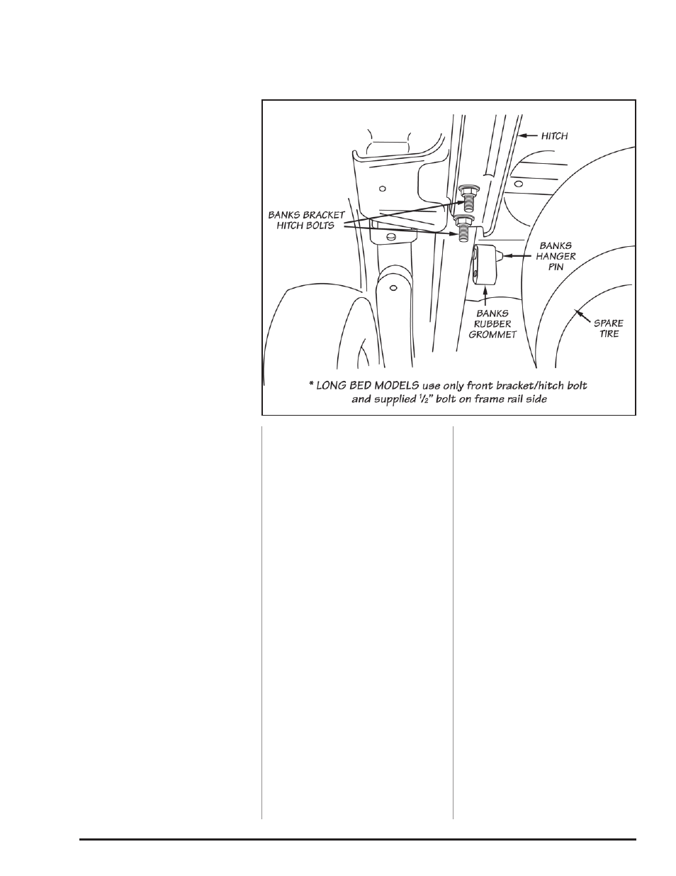
25.
Install the driver-side hanger
bracket into the rear of the driver-
side frame rail. If a hitch is installed,
remove the hitch hardware on the
driver-side, install the frame bracket
and reinstall the existing hitch
hardware.
For Long bed models, use one (1) bolt
on the flat of frame rail and one (1)
bolt on the side of the frame rail.
For Short bed models, use two (2)
bolts on the flat of the frame rail (no
bolts on the side). See Figure 6.
26.
Install the supplied rubber
grommet onto the Banks hanger
bracket.
27.
Install the driver-side tailpipe
(longer) into the top Y-pipe outlet.
Install the driver-side tailpipe hanger
into the Banks rubber grommet.
28.
Install the passenger-side
tailpipe (shorter) into the lower
Y-pipe outlet. Install the passenger-
side tailpipe hanger into the vehicle
rubber grommet.
29.
Adjust each of the pipes to
ensure that all of the hanger pins
are parallel with the frame mounted
pins and that the rubber hangers are
all positioned slightly forward (See
Figure 3). This allows the hangers
to be properly positioned once the
exhaust system reaches operating
temperature.
30.
Be sure that the two (2) tailpipes
are completely engaged into the
Y-pipe. Rotate the tailpipe until the
hanger pins are parallel with the
frame-mounted pin. Be sure both
tailpipe tips look symmetrical.
NOTE: Minimum distance between
exhaust tip and body is a half (
1
⁄
2
)
inch.
31.
Tighten the head pipe V-band
clamp to 12 ft-lbs (if previously
loosened).
32.
Align the saddle clamps on the
radius of the corresponding pipe
slots. Figure 4 illustrates the proper
location of an exhaust clamp on a
tubing joint. Torque the nuts on each
of the exhaust clamps to 35 ft-lbs.
Torque the four (4) factory flange
nuts, previously removed, to 30 ft-
lbs. Torque the hanger bracket
1
⁄
2
”
hardware to 65 ft-lbs.
33.
Using the three (3) supplied wire
ties, tie any hoses, brake lines or
harnesses a minimum of four inches
away from the exhaust/tail pipes.
34.
Remove the protective covering
from the tailpipe tip.
Caution: the protective covering
may ignite and burn if not
removed prior to running the
engine.
35.
The Banks Monster Exhaust
installation is now complete.
-END, SEcTION 1-
Figure 6 Short-bed model shown
12
96776 v.11.0