Rough Country 7500 User Manual
Page 2
INSTRUCTION SHEET
Technical Assistance - (731) 285-9000
Page 2
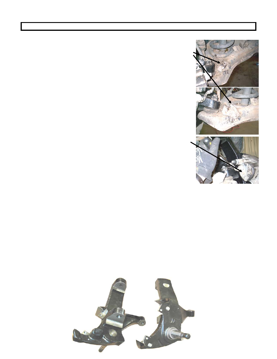
15. Using a grinder remove the factory rivets from the spindle steering stop from
the lower control arm as shown. After the Rivets are removed, use a hammer
to remove the brackets. These will need to be retained if the vehicle is
returned to stock.
16. Place the NEW driver’s side spindle on the lower ball joint and reinstall the factory
castle nut and torque to factory specs, install the new cotter pin.
17. Insert the spindle in the upper control arm and reinstall the factory castle nut and
torque to factory specs, install the new cotter pin.
18. If you have ABS please go to step 21. Slide the rubber ring on the spindle then the
dust cover with the three factory bolts. Skip step 19 and 20.
19. Separate the ABS sensor from the retaining clip in the upper control arm and slide
the ring on the spindle then the dust cover and ABS sensor. Reinstall the three
factory bolts.
20. Slide the ABS sensor wire behind the steering arm and route the wire along the
rubber brake line. Using the supplied cable ties attach the wire to the brake line.
21. CHECK THE FRONT WHEEL BEARINGS FOR WEAR AND REPLACE IF
NEEDED.
22. Put a small amount of grease on the spindle shaft and slide the rotor back on,
tighten the castle nut to factory specs and install the cotter pin.
23. Slide the brake caliper on the spindle and install the bolts to factory specs. Check
the brake line for clearance of the spindle. If necessary bend the brake line at
the caliper with a screw driver for clearance. As shown.
24. Reinstall the tie rod and torque the nut to factory specs.
25. Repeat steps 2 through 21 on passenger side of vehicle.
26. With both sides of the vehicle finished and in the air, turn the steering wheel from
side to side checking for clearance of brake lines, ABS wires and all other
components.
27. Install the tires on the vehicle and torque the lug nuts to factory specs.
28. Drive the vehicle 50 miles and recheck all bolts, wheel bearings and
clearances.
29. Have vehicle professionally aligned.
POST INSTALLATION INSTRUCTIONS
1. Check all fasteners for proper torque. Check to ensure there is adequate clearance between all rotating, mobile, fixed and
heated members. Check steering gear for interference and proper working order. Test brake system.
2. Perform steering sweep. If any obstructions you must call the tech line for assistance. If stock wheels are being used ( or
wheels with the same or greater offset, the distance between the tire sidewall and the brake hose must be checked closely.
Cycle the steering from full turn to full turn to check for clearance. If at any time the brake line comes within 1 inch or closer,
the hose must be modified accordingly. To achieve desired clearance, first bend the hoses metal end at the caliper inboard
slightly. If more clearance is needed locate and bend the metal tab as shown to the right. Check to ensure brake hoses
have sufficient slack and will not contact rotating, mobile, or fixed members, adjust lines/brackets to eliminate interference
and maintain proper working order. Failure to perform inspections may result in component failure.
3. Re torque all fasteners after 500 miles. Visually inspect components and re torque fasteners during routine vehicle service.
4. Readjust headlights to proper settings if applicable.
MAINTENANCE INFORMATION
It is the ultimate buyers responsibility to have all bolts/nuts checked for tightness after the first 100 miles and then every
1000 miles. Wheel alignment steering system, suspension and driveline systems must be inspected by a qualified
professional mechanic at least every 3000 miles.
Kit Contents:
1Ea – Lift Spindle Driver
1Ea – Lift Spindle Passenger
1Ea – Kit Bag
6Ea – Cotter Pins
2Ea – Cable Ties