Rough Country 727 User Manual
Page 3
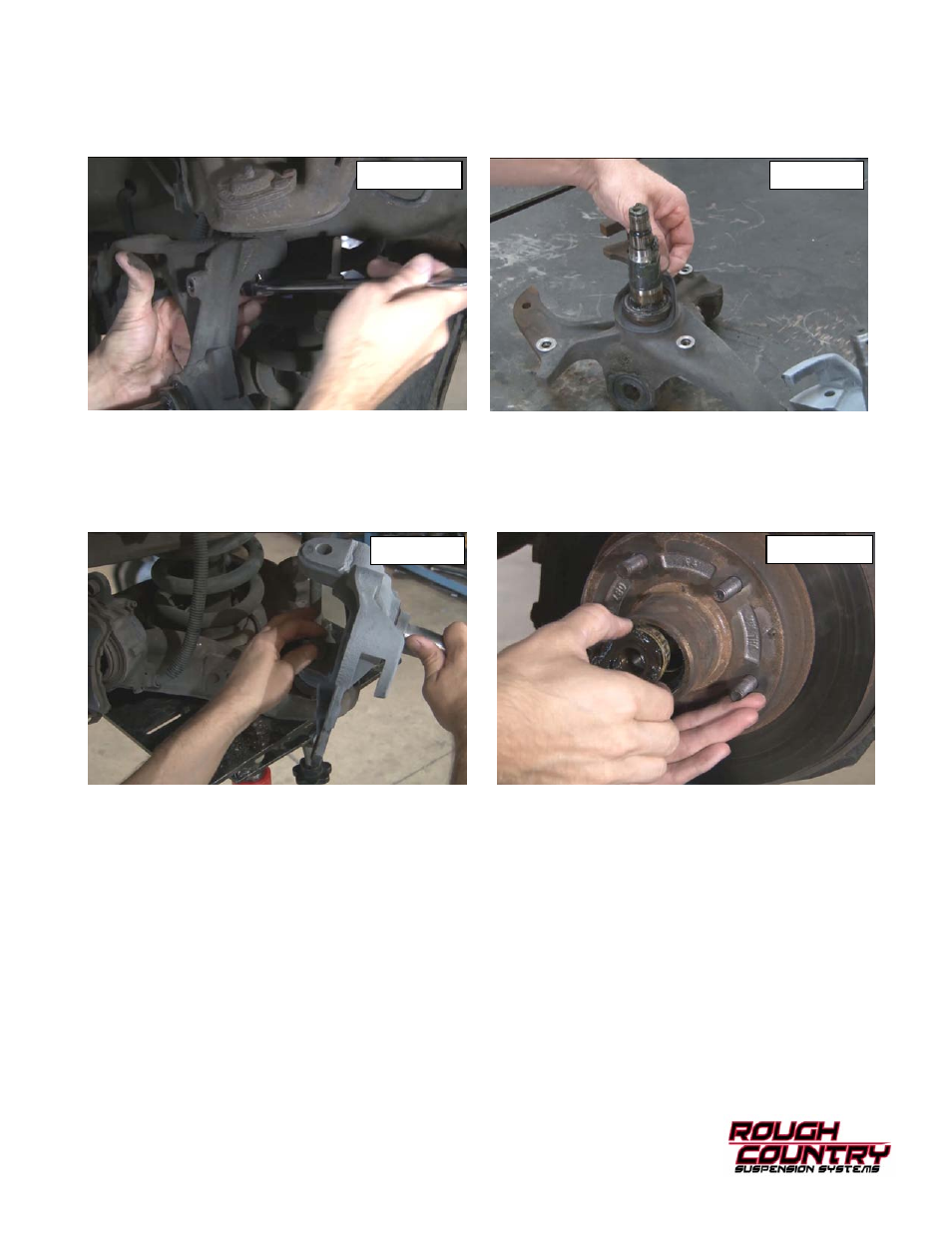
9. Remove the upper ball joint cotter pin and then loosen the upper ball joint nut using a 15/16” wrench as shown in Photo 7. Do
not remove nut.
10. Use a hammer to strike the sides of the spindle on the top and bottom ball joint to loosen the taper locks. Place a stand under the
control arm and remove the top and bottom ball joint nuts and then remove the splindle from the control arms.
11. Remove the gasket from the factory knuckle and place it on the new lowering spindle. See Photo 8.
12. Place the new lowering spindle on the lower ball joint and hand tighten factory nut. See Photo 9. Pull the upper control arm
down and attach the upper ball joint to the spindle using the factory nut. Using a 15/16” for the upper and a 7/8” for the lower
tighten the ball joint nuts and insert new supplied cotter pins.
13. Install the backing plate to the new spindle with factory bolts tighten with a 11mm and 13mm wrench. Slide the rotor assembly
and outside bearing over the spud See Photo 10 and tighten the factory nut with a pair of channel locks until the nut is snug and
the rotor still turns freely. Install new supplied cotter pin and dust cap.
14. Install the brake caliper with the factory bolts and tighten with a 3/8” allen wrench.
15. Insert the tie-rod into the spindle and tighten with a 18mm wrench. Use the new supplied cotter pin to lock the factory nut.
16. Repeat steps 3-15 on the driver side.
17. Install the tires and wheels with a 3/4” socket.
18. Jack up front of the truck to remove jack stand and lower truck to the ground.
PHOTO 7
PHOTO 8
PHOTO 9
PHOTO 10