Rough Country 636.20 User Manual
Page 4
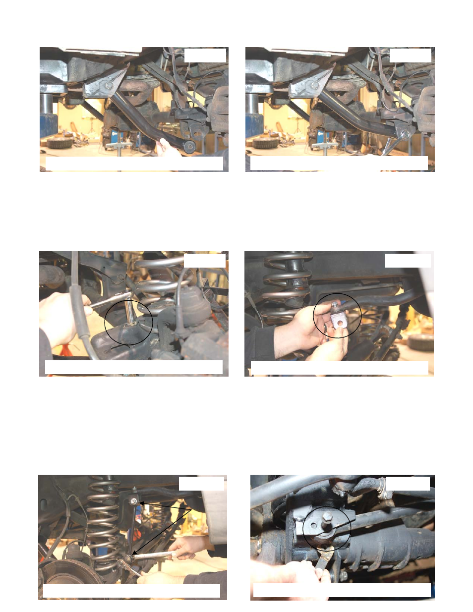
10. Using a 21mm wrench & socket install the control arms in the frame mount using stock hardware. See PHOTO 7.
11. Using a 21mm socket and 18mm wrench install the new lower control arm in the axle mount. Do not fully tighten at
this time. See PHOTO 8.
12. Install the new coil spring. A coil spring or strut compressor may be needed to install the new coil spring. Install the
new spring into the upper and lower coil spring seat. Make sure the coil spring is seated properly on the coil seat, by
rotating the spring until the pigtail end fits into the spring pocket. See PHOTO 9. Install the coil spring clip using a
13mm wrench. Torque to 16ft/lbs. Important note: If equipped with 8 cylinder motor a 3/4’ spacer kit for the
front will be installed at this time on the top of the coil spring to level the vehicle and is included with the
kits for 8 cylinder vehicles.
13. Install the new sway bar hoop on the sway bar where the stock link was secured, using the supplied 3/8” x 1 1/4” bolt
and flange lock nut. See PHOTO 10. Tighten using a 9/16” socket & wrench.
14. Install the bushings and 12mm sleeves on the top and bottom of the sway bar link. Install the upper link in the hoop
bracket with the 12mm bolts and nuts with the head of the bolt toward the frame and threads facing outward.
Install the lower link using the stock axle hardware. Tighten using a 18mm and 19mm wrench. See PHOTO 11.
15. Assemble the front shock absorbers, part # 651896 hydro / 651997 Nitro and install using the factory hardware on
the bottom of the shock. Torque to 20 ft/lbs .Install the upper stud bushings and tighten the upper mounting point
until bushing swells slightly Repeat for opposite side.
16. Install the tires/wheels and lug nuts, using a 13/16” deep wheel socket. Lower the vehicle to the ground.
17. Tighten the lower control arms, using a 21mm socket and 21mm /18mm wrench. Torque to 130 ft/lbs.
18. Install the track bar in the axle mount location as shown in PHOTO 12 and tighten with stock hardware. Turning the
steering wheel either left and right will align the hole.
PHOTO 7
PHOTO 8
PHOTO 9
PHOTO 10
PHOTO 11
PHOTO 12
INSTALL THE LOWER CONTROL ON FRAME
INSTALL THE ARM ON THE AXLE
INSTALL THE COIL SPRING
INSTALL THE UPPER SWAY BAR BRACKET
INSTALL THE LINK ON THE AXLE
REINSTALL THE TRACK ROD