Rough Country 864 User Manual
Page 2
1. Jack up the front of the vehicle and support the vehicle with jack stands, so that the front wheels are off the ground
2. Using 13/16” socket remove the front tires/wheels.
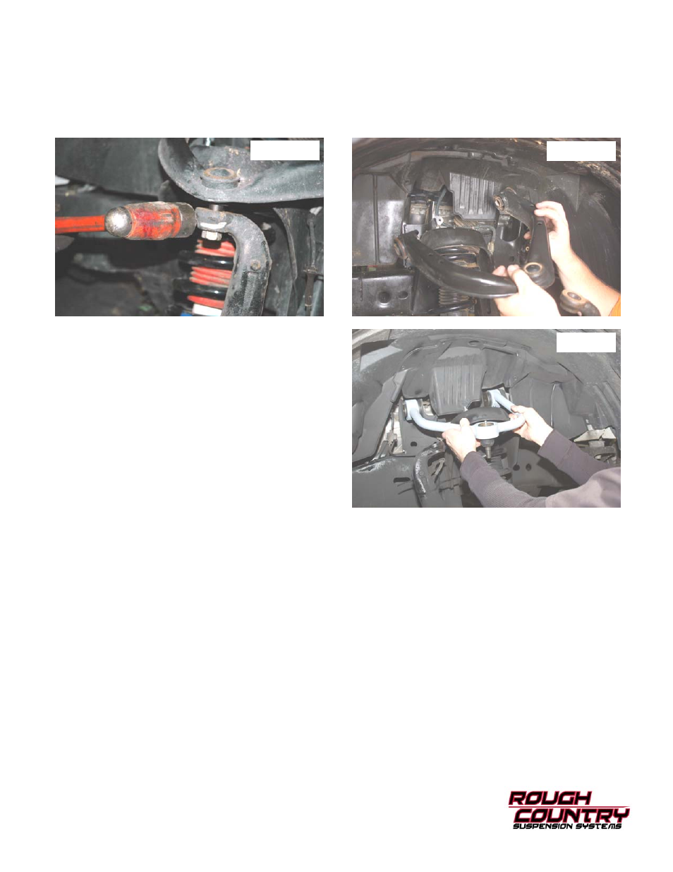
3. Remove cotter pin from the upper control arm ball joint nut. Place jack stand under the knuckle for support. Using 22
mm socket remove nut. Using a hammer hit the knuckle as shown to allow the ball joint to separate from the upper
control arm See Photo 1. Do not allow the knuckle to pull out far enough that it pulls the shaft out of the differential.
4. Remove the upper control arm as shown in Photo 2 using a 19mm wrench. Retain the factory hardware for reuse.
5. Grind the tabs on the inner side of the control arm pockets
to allow the new control arms to be installed. Failure to
complete this task will not allow the new control arms
to be installed.
6. Install the control arms in the factory location with the fac-
tory hardware. See Photo 3. Do not tighten at this time.
7. Using a floor jack, raise the lower control arm and connect
the upper ball joint on the upper control arm to the spindle.
Install the castle nut. Install the cotter pin and tighten using
a 22mm wrench to the factory specifications.
INSTALLATION INSTRUCTIONS
Photo 1
Photo 2
Photo 3
1. Check all fasteners for proper torque. Check to ensure there is adequate clearance between all rotating, mobile,
fixed and heated members. Check steering for interference and proper working order. Test brake system.
2. Perform steering sweep. The distance between the tire sidewall and the brake hose must be checked closely. Cycle
the steering from full turn to full turn to check for clearance. Failure to perform inspections may result in component
failure.
3. Re torque all fasteners after 500 miles. Visually inspect components and re torque fasteners during routine vehicle
service.
POST INSTALLATION INSTRUCTIONS