Rough Country 283N2 User Manual
Page 2
3. Use extreme caution when loading and unloading the torsion bars;
there is a tremendous amount of energy stored in them. Keep your
hands and body clear of the adjuster arm assembly and the puller
tool in case anything slips or breaks. Note: Because of the extreme
loads generated by the torsion bars on these vehicles, a standard
tow-jaw puller may bend the “lips” of the cross member and my pop
out of place. For best results use a c-clamp type puller tool. If you
cannot find one locally, this tool (J-22517-C) is available from Kent
Moore Tools in Roseville, Michigan (800-345-2233) or a Ball Joint
Remover like OTC7249 can be used.
4. On the driver side, using a torsion bar removal tool, remove the
stock torsion bar adjuster by loading the torsion bar using the tool
and removing the bolt and nut block. Slide the torsion bar forward allowing the OE torsion key to fall out.
5. Install the new torsion bar adjuster using the torsion bar tool. Reinstall the threaded block and adjuster bolt.
6. Repeat steps for passenger side. Making sure the driver and passenger side torsion bar adjuster bolts are adjusted
the same amount. Fine-tuning is done in a later step.
7. Remove the factory shock absorbers, and discard.
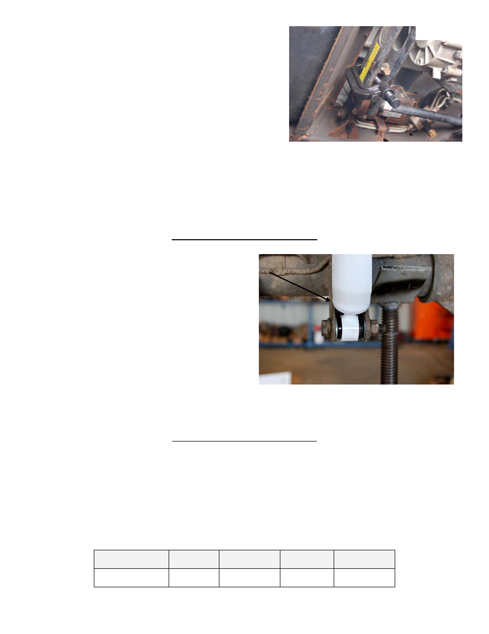
8. Locate shock part # 658520 (RCX#660566) from kit box. Install the supplied shock and bushings in the factory
location using the factory bolt on the lower end of the shock.
9. Jack up the front of the vehicle and remove the jack stands. Lower the vehicle to the ground to where the torsion bars
are supporting the weight of the vehicle.
REAR INSTALLATION INSTRUCTIONS
1. Chock the front wheels and jack up the rear of the vehicle. Support the vehicle with approved jack stands.
2. Remove the factory shocks and discard. Support the rear
axle with a jack. Loosen the passenger u bolts.
3. Remove the drivers side u bolts.
4. Lower the jack and remove factory block and continue to
lower the axle until the lift block can be installed (don’t
reuse factory block). The small end of the block faces the
front of the truck.
5. Install the new u bolts, washers, and nuts. Do not tighten at
this time.
6. On the passenger side remove the u bolts and lower the
jack and install the lift block.
7. Tighten u-bolts, alternating from bolt to bolt. Torque ½” u-
bolts to 65 ft./lbs. and 9/16” u-bolts to 87 ft. /lbs., or 5/8” u-
bolts to 120 ft./lbs.
8. Grinding may be required on the driver side e-brake bracket
on the lower shock mount. If needed grind the threads to make sure there is no interference with the shock absorber
or remove the bolt from the lower shock mount
9. Install the new shocks part # 650380 (RCX#660567), using the supplied bushings and sleeves, and factory hardware.
10. Install the wheels and tires. Lower the vehicle to the ground.
POST INSTALLATION INSTRUCTIONS
After the torsion bar adjusters have been installed and tightened to the factory measurement taken in step #2. additional
adjustment may need to be performed to level the vehicle. This is done by either tightening or loosening the torsion bar
adjuster bolts. Use a floor jack to support the side of the vehicle that is being adjusted, raising the tires slightly of the
ground and only adjusting the bolt 1-2 turns at a time to ensure the leveling of the truck. After adjustment lower the vehicle
to the ground and recheck for level. This may take several attempts.
As with any lift installed, adjustment of the front
headlights is required after installation. Note – the air dam on the front may need to be trimmed for additional clearance,
depending on the tire size.
A front-end alignment should ALWAYS be checked after installing ANY vehicle suspension lift. This kit typically requires a
slight toe-in adjustment. Record the ride height measurement at the time of alignment. If, in the future the torsion bars
settle excessively, alignment can be restored by adjusting-up the bars to their original ride height.
Alignment Specs
Caster Left
Caster Right
Camber Left
Camber Right
2 2.5 0 -1/4
Photo 2