Velleman KSR5 User Manual
Page 5
KSR5 VELLEMAN
5
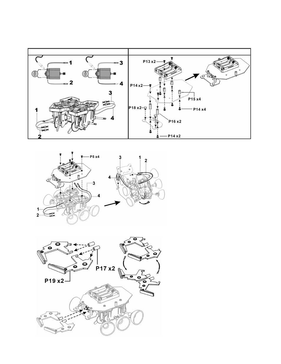
c) Mechanical Assembly
1. Mount the wires and the ceramic capacitors type 104 on the motors and fix the battery holder on the PCB.
Connect the battery holder to the battery connector (BAT, see "4.a) PCB assembly").
The colour code used for the wires is: 1=green, 2=yellow, 3=orange, 4=blue
wires / capacitors
battery holder
2. Fix the PCB to the gearbox and put the wires through the holes at the front of the device.
3. Mount the antennae (2 ways are possible):
Fig. 7
Fig. 6
Fig. 8
Fig. 9