Velleman KSR5 User Manual
Page 2
KSR5 VELLEMAN
2
4. Assembly
a) PCB Assembly
Start the assembly by mounting the jumper wires and resistors. The components codes are printed on the PCB:
Part ID
Description
Colour Code
Quantity
J1~16
jumper wire
n.a.
16
R16~19
10Ω
brown/black/black/gold
4
R1/4~7/12~15
10K
brown/black/orange/gold
9
R8~11
22K
red/red/orange/gold
4
R2/3
1M
brown/black/green/gold
2
Mount the capacitors, transistors and diodes next:
Part ID
Description
Quant.
C7
ceramic capacitor 103
1
C1~6
ceramic capacitor 104
6
EC1~3
electrolytic capacitor 0.47µ f
3
EC4
electrolytic capacitor 10µ f
1
Q5~8
transistor C945
4
Q9~12
transistor 8050
4
Q1~4
transistor 8550
4
D1~4/7/8
diode 1N4004
6
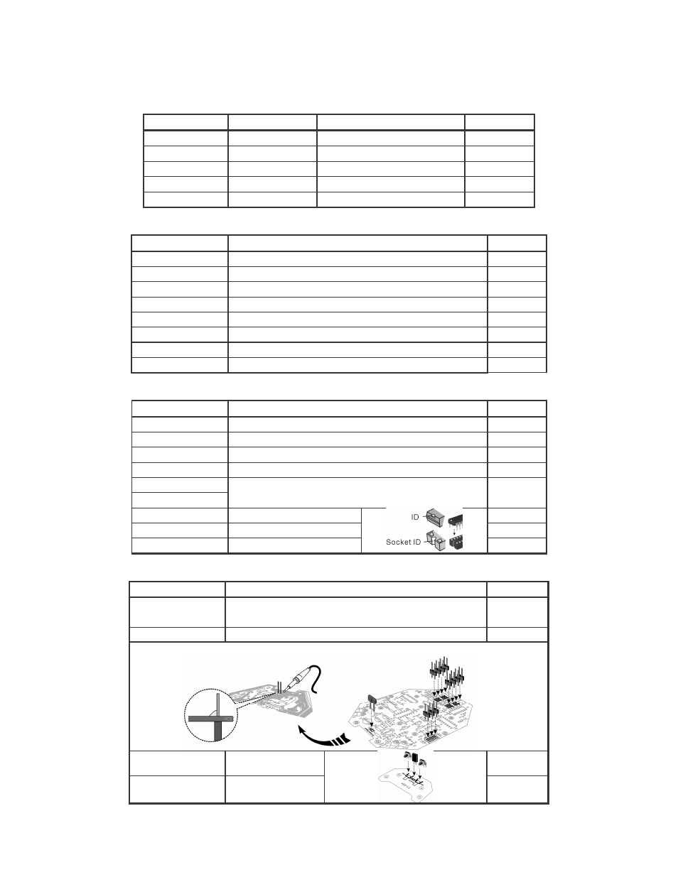
Mount the IC sockets, the battery connector, the slide switch, the pins and the ICs.
Part ID
Description
Quant.
IC1
8 pins IC socket (fig.1 #16)
1
IC2~6
16 pins IC socket (fig.1 #14)
5
BAT.
battery connector (fig.1 #11)
1
SW.
slide switch (fig.1 #21)
1
M1 (+/-)
M2 (+/-)
pins (fig.1 #18)
4
IC1
555 (8 pins)
1
IC2/3
74LS109AP (16 pins)
2
IC4~6
74HC157AP (16 pins)
3
Mount the pin headers on the main PCB and a pin header and the tactile switches on the small PCB:
Part ID
Description
Quantity
TJ1~3
MOVEMENT 1/2
pin header 2 pins (fig.1 #10)
11
To down board
pin header 2 pins (fig.1 #8)
1
REMARK:
Touch B
female header
1
SW1/2
tactile switch
2
Fig. 3