Voltage regulator test circuit – Velleman DCA75 User Manual
Page 44
Atlas DCA Pro User Guide
December 2012 – Rev 1
Page 44
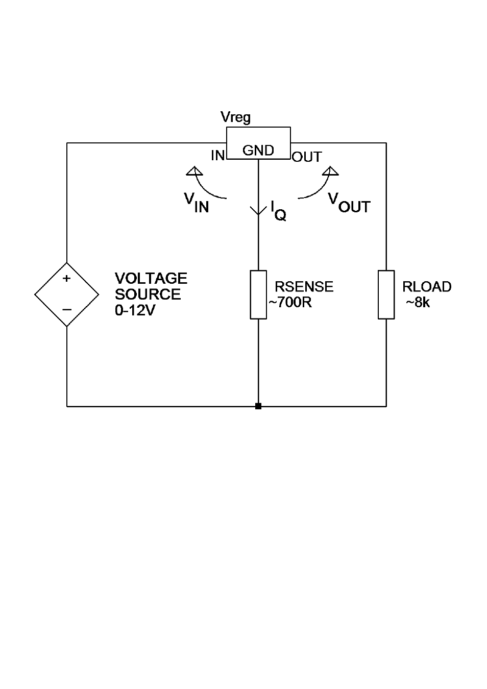
Voltage Regulator Test Circuit
The test circuit shown here is used for the analysis of voltage
regulators (positive regulators in this example). Note that the range of
regulator voltages supported will depend on the quiescent current (I
Q
).
A higher quiescent current will cause more voltage to be dropped
across the sense resistor and yield less voltage for the regulator itself.
Note also that some voltage regulators, particularly low dropout types
(LDO), are not stable when tested by the DCA Pro.
See also other documents in the category Velleman Accessories for electrical:
- PS1502A (6 pages)
- VMB6PBN (15 pages)
- VTTEST14 (5 pages)
- VMB3PS (10 pages)
- PSSE60 (18 pages)
- VMB8IR (10 pages)
- PSSE24 (4 pages)
- VMBLCDWB (12 pages)
- VMB1TSW (24 pages)
- VL3288 (5 pages)
- PSSMV24 (23 pages)
- VMB4IRT (16 pages)
- VMB7IN (8 pages)
- VMB1USB (6 pages)
- PSI600B (29 pages)
- VL06LA (4 pages)
- PSSEUSB6A (2 pages)
- PS603 (17 pages)
- VMB1TS (43 pages)
- PSSE23 (4 pages)
- VL1212 (29 pages)
- VL7168 (7 pages)
- PSSE45 (19 pages)
- PS925 (13 pages)
- VMB1BL (12 pages)
- VMB1RS (6 pages)
- PSS1320 (11 pages)
- PSSMV8 (20 pages)
- VMB8PB (16 pages)
- VMB4RF (8 pages)
- VMBRSUSB (8 pages)
- PI300BN (33 pages)
- VMBGPTCx (12 pages)
- PSC1350 (2 pages)
- VTTEST15 (7 pages)
- PSSEUSB4 (2 pages)
- VMB4DC (18 pages)
- VMBGP1x (12 pages)
- PSSMV2 (4 pages)
- VMB8PBU (12 pages)
- PSIC75B (18 pages)
- PS12015 (5 pages)
- VMB4TX (1 page)
- VL6278 (12 pages)
- VMB4PD (35 pages)