Diode networks – Velleman DCA75 User Manual
Page 10
Atlas DCA Pro User Guide
December 2012 – Rev 1
Page 10
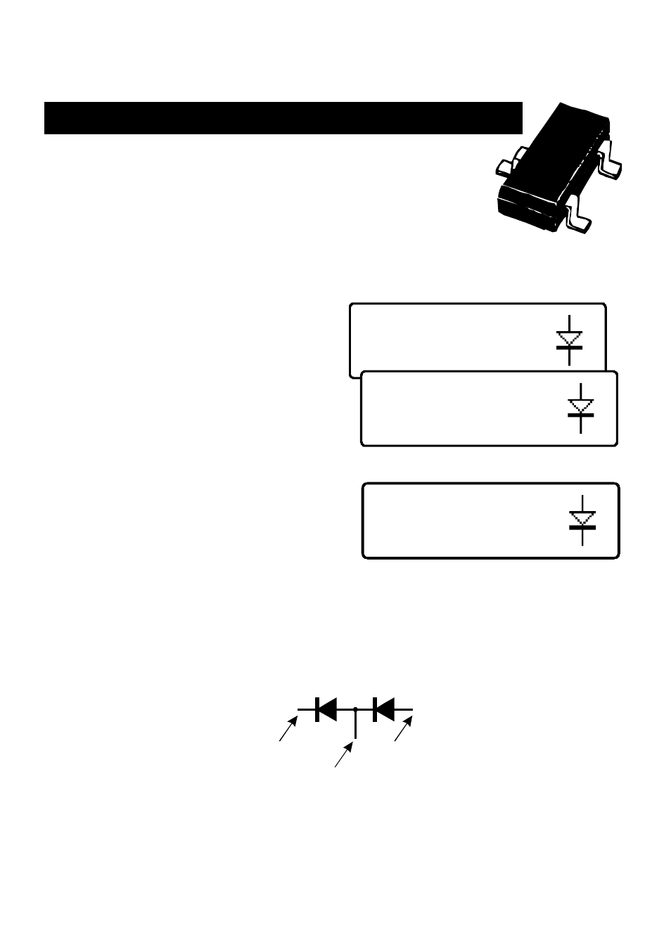
2 diode junctions
#1: Diode junction
Green-K Blue-A
#1: Diode junction
Green-K Blue-A
VF=0.699V at 5.00mA
#2: Diode junction
Red-A Blue-K
VF=0.683V at 5.00mA
Diode Networks
The DCA Pro will identify multiple diode junctions
between the probes. For three terminal devices such as
SOT-23 diode networks, all three test clips must be
connected.
The instrument will show the results for each diode junction in turn.
Firstly, the unit will show that it has
found a number of diode junctions:
The details for the first diode are then
displayed (Diode #1). In this example,
the Green test clip is on the Cathode of
diode #1 and the Blue test clip is on the
Anode.
The details for the second diode are
then displayed (by briefly pressing
scroll-off):
It can be seen in the above example, that the blue test clip is connected to both
the anode on Diode #1 and to the cathode of Diode #2. This means that the two
diodes are effectively connected in series, with the blue clip at the mid point.
This example is illustrated below:
#1
Green
Red
Blue
#2
In the same way as the single diode analysis, the forward voltage for each
diode is measured for a nominal test current of 5mA.