Junction fets (jfets) – Velleman DCA75 User Manual
Page 25
Atlas DCA Pro User Guide
December 2012 – Rev 1
Page 25
VGS(off)=-6.65V
at ID=1uA
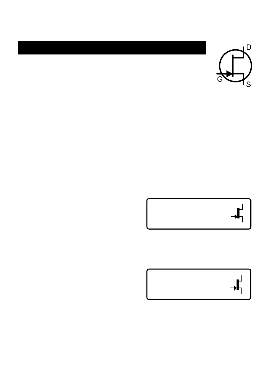
Junction FETs (JFETs)
Junction FETs are conventional Field Effect Transistors.
The voltage applied across the gate-source terminals controls
current between the drain and source terminals. N-Channel
JFETs require a negative voltage on their gate with respect to their source, the
more negative the voltage, the less current can flow between the drain and
source.
Unlike Depletion Mode MOSFETs, JFETs have no insulation layer on the gate.
This means that although the input resistance between the gate and source is
normally very high (greater than 100MΩ), the gate current can rise if the
semiconductor junction between the gate and source or between the gate and
drain become forward biased. This can happen if the gate voltage becomes
about 0.6V higher than either the drain or source terminals for N-Channel
devices or 0.6V lower than the drain or source for P-Channel devices.
The internal structure of JFETs is
essentially symmetrical about the gate
terminal, this means that the drain and
source
terminals
are
often
indistinguishable by the DCA Pro. The JFET type, gate terminal and measured
parameters are displayed however.
Pinch-Off
A common parameter to be specified
for JFETs is “Pinch-Off”. This is the
voltage needed between the gate-source
to turn off the JFET. The DCA Pro will
determine that the JFET is off when the drain current is less than 1µA.
N-Ch Junction FET
Green-G
Symmetrical Src/Drn