Velleman KSR2 User Manual
Page 3
KSR2 VELLEMAN
3
Q2/4
transistor 8050
2
Q1/3
transistor 1815 (or C945)
2
VR
variable resistor 100K
1
MIC
microphone 1
IC1
IC 4069
1
IC2
IC 4017
1
SW
slide switch
1
ML + -
MR + -
3V +
9V +
G
Ø1.3mm pin
8
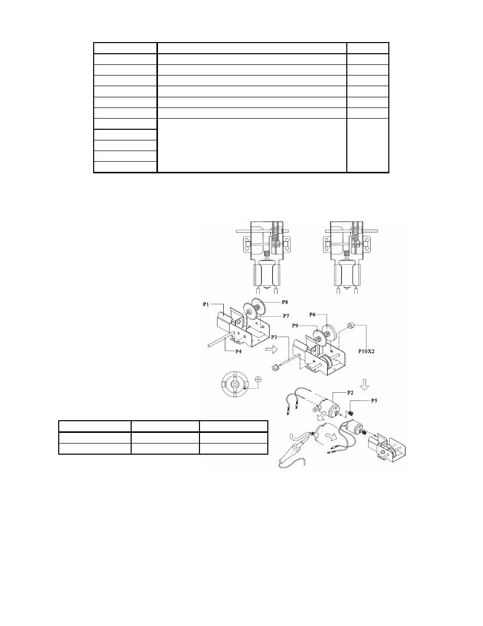
b) Gearbox Assembly
Part ID
Motor’s “+” Pole Motor’s “-” Pole
right gearbox
yellow wire
blue wire
left gearbox
orange wire
green wire
Note that the protruding edge should be pointed towards the metal case. The yellow wire is the positive (+) pole of
the motor, the green wire is the negative pole (-).
Fig. 3
right gearbox
after assembly
left gearbox
after assembly