Velleman KSR2 User Manual
Page 2
KSR2 VELLEMAN
2
12
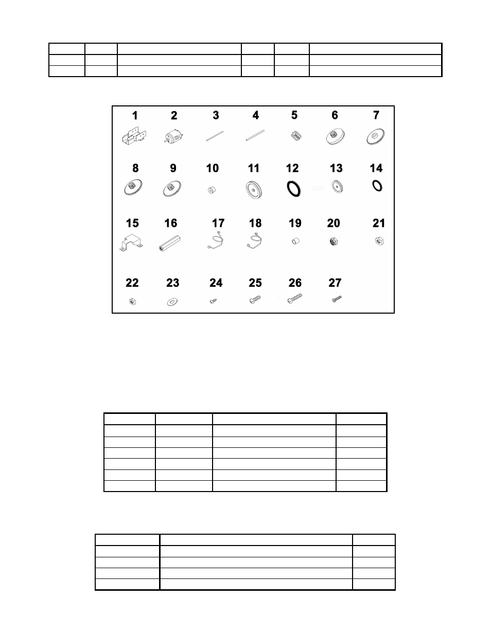
2 rubber
tyre 26
1
screw (M3 x 16mm)
13
1
front wheel (Ø20mm)
27
5
screw (M2 x 10mm)
14
1
rubber ring (Ø15 x 2.5mm)
28
1
wooden plate (included)
4. Assembly
a) PCB Assembly
Start the assembly by mounting the resistors. The names of all components have been printed on the PCB. Consult
the table below :
Part ID
Description.
Colour Code
Quantity
R10/13
100
Ω
brown/black/brown/gold 2
R8/11
4.7K yellow/violet/red/gold 2
R1
10K brown/black/orange/gold 1
R7
22K red/red/orange/gold 1
R2/4/6/9/12
33K orange/orange/orange/gold 5
R3/5
2.7M red/violet/green/gold 2
Mount the diodes, capacitors, transistors, the variable resistor, the IC’s, the slide switch and the pins next. Consult
the table below :
Part ID
Description
Quant.
D1/2/3/4/5/6
diodes IN 4148
6
C2
ceramic capacitor 47P
1
C1
mylar capacitor 103
1
C3/4
electrolytic capacitor 1uf
2
Fig. 2