Vishay semiconductors, Phase control thyristors (stud version), 80 a, Ordering information table – C&H Technology 82RIA...PbF Series User Manual
Page 7
www.vishay.com
For technical questions within your region, please contact one of the following:
Document Number: 94392
6
,
,
Revision: 17-Sep-10
80RIA...PbF, 81RIA...PbF, 82RIA...PbF Series
Vishay Semiconductors
Phase Control Thyristors
(Stud Version), 80 A
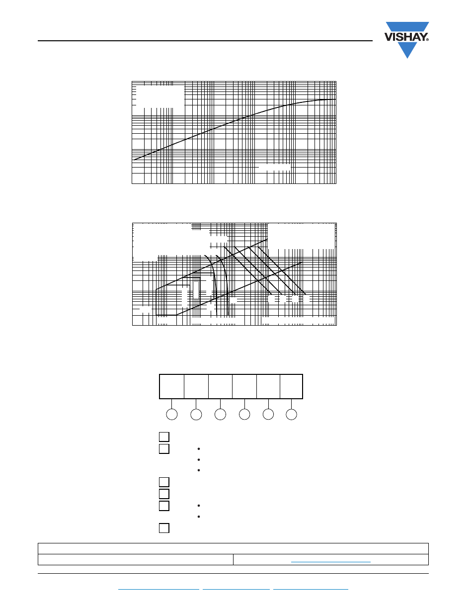
Fig. 8 - Thermal Impedance Z
thJC
Characteristics
Fig. 9 - Gate Characteristics
ORDERING INFORMATION TABLE
LINKS TO RELATED DOCUMENTS
Dimensions
www.vishay.com/doc?95362
0.001
0.01
0.1
1
0.0001
0.001
0.01
0.1
1
10
Sq uare Wave Pulse Duration (s)
th
J
C
80RIA Series
Steady State Value
R = 0.30 K/W
(DC Operation)
Tr
an
si
e
n
t T
h
e
rm
a
l I
m
pe
da
n
c
e
Z
(K
/W
)
thJC
0.1
1
10
100
0.001
0.01
0.1
1
10
100
1000
VGD
IGD
(b)
(a)
Tj=25 °C
Tj=125 °C
Tj=-40 °C
(1)
(2)
(3)
Instantaneous Gate Current (A)
In
st
an
ta
ne
ou
s G
a
te
V
o
lt
ag
e
(
V
)
Rectangular gate pulse
a) Recommended load line for
b) Recommended load line for
Frequency Limited by PG(AV)
tr<=1 µs
rated di/dt : 20V, 30ohms; tr<=0.5 µs
<=30% rated di/dt : 20V, 65ohms
(1) PGM = 100W, tp = 500µs
(2) PGM = 50W, tp = 1ms
(3) PGM = 20W, tp = 2.5ms
(4) PGM = 10W, tp = 5ms
Device: 80RIA Series
(4)
1
-
I
TAV
x 10 A
3
-
RIA = Essential part number
4
6
-
Lead (Pb)-free
-
Voltage code x 100 = V
RRM
(see Voltage Ratings table)
5
-
None = Stud base 1/2"-20UNF- 2 A threads
M = Stud base metric threads M12 x 1.75 E 6
2
-
0 = Eyelet terminals (gate and auxiliary cathode leads)
1 = Fast-on terminals (gate and auxiliary cathode leads)
2 = Flag terminals (gate and auxiliary cathode terminals)
Device code
5
1
3
2
4
6
8
0
RIA
120
M
PbF