Vishay semiconductors, Phase control thyristors (stud version), 80 a, Conduction – C&H Technology 82RIA...PbF Series User Manual
Page 5
www.vishay.com
For technical questions within your region, please contact one of the following:
Document Number: 94392
4
,
,
Revision: 17-Sep-10
80RIA...PbF, 81RIA...PbF, 82RIA...PbF Series
Vishay Semiconductors
Phase Control Thyristors
(Stud Version), 80 A
Note
• The table above shows the increment of thermal resistance R
thJC
when devices operate at different conduction angles than DC
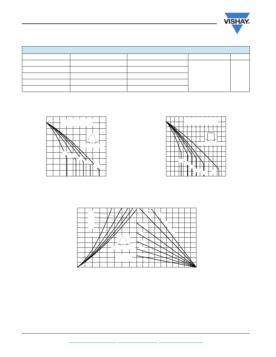
Fig. 1 - Current Ratings Characteristics
Fig. 2 - Current Ratings Characteristics
Fig. 3 - On-State Power Loss Characteristics
R
thJC
CONDUCTION
CONDUCTION ANGLE
SINUSOIDAL CONDUCTION
RECTANGULAR CONDUCTION
TEST CONDITIONS
UNITS
180°
0.042
0.030
T
J
= T
J
maximum
K/W
120°
0.050
0.052
90°
0.064
0.070
60°
0.095
0.100
30°
0.164
0.165
80
90
100
110
120
130
0
10
20
30
40
50
60
70
80
90
M
a
x
imu
m
A
llo
wabl
e
C
a
se
T
e
mp
e
ratu
re
(
°C
)
30°
60°
90°
120°
180°
Average On-state Current (A)
Conduc tion Angle
80RIA Series
R (DC) = 0.30 K/W
thJC
70
80
90
100
110
120
130
0
20
40
60
80
100
120
140
DC
30°
60°
90°
120°
180°
Average On-state Current (A)
Ma
x
im
u
m A
llo
w
a
b
le Ca
se
T
e
m
p
e
ra
tu
re
(
°C
)
Cond uc tion Period
80RIA Series
R (DC) = 0.30 K/W
thJC
0
25
50
75
100
125
Maximum Allowable Ambient Temperature (°C)
0.6
K/
W
1
K/W
2 K/
W
5 K/W
3 K/ W
1.4
K/ W
R
=
0
.4
K
/W
-
D
e
lta
R
th
SA
0
10
20
30
40
50
60
70
80
90
100
110
120
0
10
20
30
40
50
60
70
80
180°
120°
90°
60°
30°
RMS Limit
Cond uction Angle
M
a
x
im
u
m
A
v
e
ra
g
e
O
n
-s
ta
te
P
o
w
e
r L
o
ss
(
W
)
Average On-state Current (A)
80RIA Series
T = 125°C
J