Vishay semiconductors, Phase control thyristors (stud version), 80 a – C&H Technology 82RIA...PbF Series User Manual
Page 6
Document Number: 94392
For technical questions within your region, please contact one of the following:
www.vishay.com
Revision: 17-Sep-10
,
,
5
80RIA...PbF, 81RIA...PbF, 82RIA...PbF Series
Phase Control Thyristors
(Stud Version), 80 A
Vishay Semiconductors
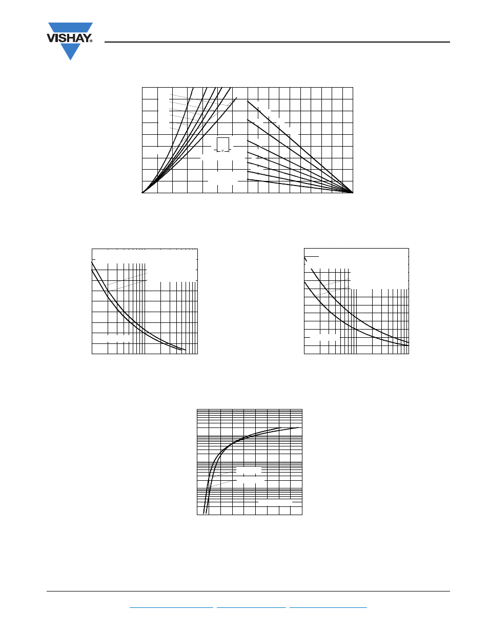
Fig. 4 - On-State Power Loss Characteristics
Fig. 5 - Maximum Non-Repetitive Surge Current
Fig. 6 - Maximum Non-Repetitive Surge Current
Fig. 7 - On-State Voltage Drop Characteristics
0
25
50
75
100
125
Maximum Allowable Ambient Temperature (°C)
R
=
0.4
K/
W
- D
elt
a
R
th
SA
0.6
K/W
1 K
/ W
1.4
K/W
2 K/ W
3 K/ W
5 K/ W
0
20
40
60
80
100
120
140
160
180
0
20
40
60
80
100
120
140
DC
180°
120°
90°
60°
30°
RMS Limit
Conduc tion Period
Ma
x
im
u
m
A
v
e
ra
g
e
O
n
-s
ta
te
P
o
w
e
r L
o
ss
(W
)
Average On-state Current (A)
80RIA Series
T = 125°C
J
800
1000
1200
1400
1600
1800
1
10
100
Number Of Eq ua l Amp litud e Half Cyc le Current Pulses (N)
P
e
a
k
H
a
lf
S
in
e
W
a
v
e
On
-s
ta
te
C
u
rr
e
n
t (
A
)
at 60 Hz 0.0083 s
at 50 Hz 0.0100 s
80RIA Series
At Any Rated Load Condition And With
Rated V Applied Following Surge.
RRM
Initial T
J
= 125°C
700
800
900
1000
1100
1200
1300
1400
1500
1600
1700
1800
1900
2000
0.01
0.1
1
Pulse Train Duration (s)
Versus Pulse Train Duration. Control
Of Conduction May Not Be Maintained.
P
e
a
k
H
a
lf
S
in
e
W
a
v
e
O
n
-s
ta
te C
u
rr
e
nt (
A
)
Initial T = 125°C
No Voltage Reapplied
Rated V Reapplied
RRM
J
80RIA Series
Maximum Non Repetitive Surge Current
1
10
100
1000
10000
0.5
1
1.5
2
2.5
3
3.5
4
4.5
5
T = 25°C
J
In
st
an
ta
ne
ou
s O
n
-s
ta
te
C
u
rr
e
n
t (
A
)
Instantaneous On-state Voltage (V)
T = 125°C
J
80RIA Series