Vishay high power products, Half bridge" igbt mtp (ultrafast npt igbt), 80 a – C&H Technology 40MT120UHTAPbF User Manual
Page 4
Document Number: 94507
For technical questions, contact:
www.vishay.com
Revision: 01-Mar-10
3
40MT120UHAPbF, 40MT120UHTAPbF
"Half Bridge" IGBT MTP
(Ultrafast NPT IGBT), 80 A
Vishay High Power Products
Notes
(1)
T
0
, T
1
are thermistor´s temperatures
(2)
, temperature in Kelvin
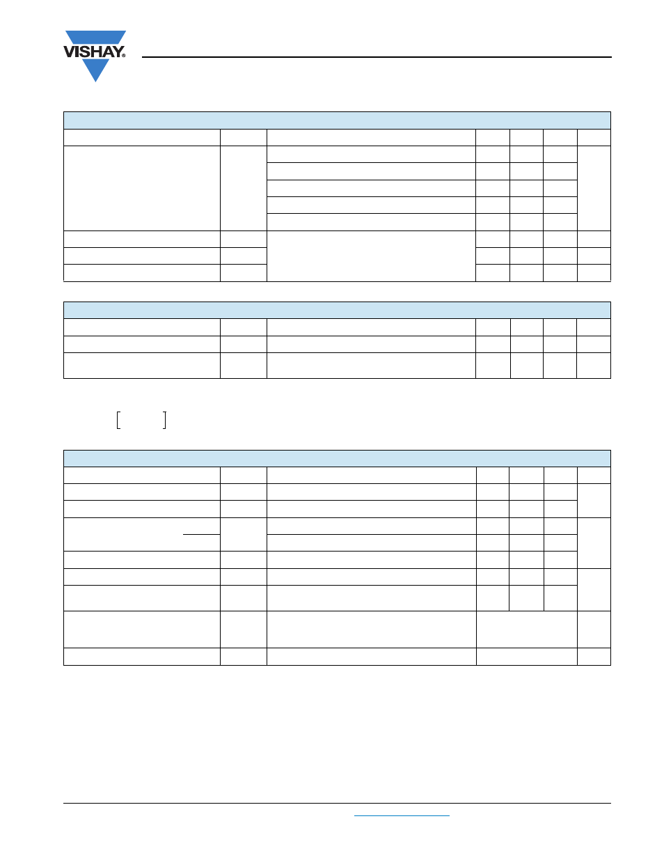
DIODE SPECIFICATIONS (T
J
= 25 °C unless otherwise specified)
PARAMETER
SYMBOL
TEST CONDITIONS
MIN.
TYP.
MAX.
UNITS
Diode forward voltage drop
V
FM
I
C
= 40 A
-
2.98
3.38
V
I
C
= 80 A
-
3.90
4.41
I
C
= 40 A, T
J
= 125 °C
-
3.08
3.39
I
C
= 80 A, T
J
= 125 °C
-
4.29
4.72
I
C
= 40 A, T
J
= 150 °C
-
3.12
3.42
Reverse recovery energy of the diode
E
rec
V
GE
= 15 V, R
g
= 5
Ω, L = 200 μH
V
CC
= 600 V, I
C
= 40 A
T
J
= 125 °C
-
574
861
μJ
Diode reverse recovery time
t
rr
-
120
180
ns
Peak reverse recovery current
I
rr
-
43
65
A
THERMISTOR SPECIFICATIONS (40MT120UHTAPbF only)
PARAMETER
SYMBOL
TEST CONDITIONS
MIN.
TYP.
MAX.
UNITS
Resistance
R
0
(1)
T
0
= 25 °C
-
30
-
k
Ω
Sensitivity index of the
thermistor material
β
(1)(2)
T
0
= 25 °C
T
1
= 85 °C
-
4000
-
K
R
0
R
1
-------
β 1
T
0
------
1
T
1
------
–
⎝
⎠
⎛
⎞
exp
=
THERMAL AND MECHANICAL SPECIFICATIONS
PARAMETER
SYMBOL
TEST CONDITIONS
MIN.
TYP.
MAX.
UNITS
Operating junction temperature range
T
J
- 40
-
150
°C
Storage temperature range
T
Stg
- 40
-
125
Junction to case
IGBT
R
thJC
-
-
0.29
°C/W
Diode
-
-
0.61
Case to sink per module
R
thCS
Heatsink compound thermal conductivity = 1 W/mK
-
0.06
-
Clearance
(1)
External shortest distance in air between 2 terminals
5.5
-
-
mm
Creepage
(2)
Shortest distance along external surface of the
insulating material between 2 terminals
8
-
-
Mounting torque to heatsink
A mounting compound is recommended and the
torque should be checked after 3 hours to allow for
the spread of the compound. Lubricated threads.
3 ± 10 %
Nm
Weight
66
g