Vishay dale, Dimensions in inches [millimeters, Material specifications – Vishay Lead LVR User Manual
Page 2: Surface temperature vs power, Tcr vs. resistance value, Derating performance
LVR
Wirewound Resistors, Precision Power, Low Value,
Commercial, Military, MIL-PRF-49465 Type RLV, Axial Lead
Vishay Dale
Document Number: 30206
For technical questions, contact: [email protected]
www.vishay.com
Revision: 29-Feb-08
153
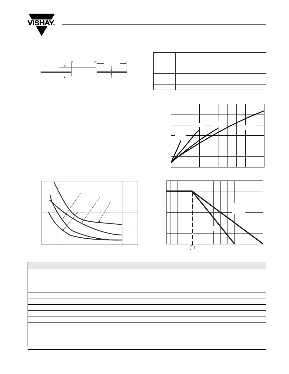
DIMENSIONS in inches [millimeters]
Note
(1)
On some standard reel pack methods, the leads may be trimmed to a shorter length than shown
MATERIAL SPECIFICATIONS
Element: Self-supporting nickel-chrome alloy
(LVR10 also utilizes manganin)
Encapsulation: High temperature mold compound
Terminals: Tinned copper
Part Marking: DALE, model, wattage, value, tolerance,
date code
The improved TCR characteristics of these LVR models from
- 55 °C to + 125 °C (reference to + 25 °C) are as follows:
1.50 [38.10]
(1)
minimum
A
C
B
MODEL
DIMENSIONS in inches [millimeters]
A
± 0.010 [0.254]
B
± 0.010 [0.254]
C
± 0.002 [0.051]
LVR01
0.427 [10.85]
0.115 [2.92]
0.020 [0.508]
LVR03
0.560 [14.22]
0.205 [5.21]
0.032 [0.813]
LVR05
0.925 [23.50]
0.330 [8.38]
0.040 [1.02]
LVR10
1.828 [46.43]
0.392 [9.96]
0.040 [1.02]
1
2
3
4
5
6
7
8
9
10
250
200
150
100
50
NI
E
R
U
T
A
R
E
P
M
E
T
E
C
A
F
R
U
S
°
C
POWER IN W
LVR03
LVR01
Surface Temperature vs Power
LVR05
LVR10
20 40 60 80 100
RESISTANCE (
Ω x 10
-3
)
LVR05
400
300
200
100
TCR IN ppm/
°C
LVR03
LVR01
TCR vs. Resistance Value
LVR10
- 65
- 25
25
75
125
175
225
275
AMBIENT TEMPERATURE IN °C
120
100
80
60
40
20
0
%
N I
R
E
W
O
P
D
E
T
A
R
LVR01
LVR03
LVR05
LVR10
Derating
PERFORMANCE
TEST
CONDITIONS OF TEST
TEST LIMITS
Thermal Shock
- 65 °C to + 125 °C, 5 cycles, 15 min at each extrem
± (0.2 % + 0.0005
Ω) ΔR
Short Time Overload
5 x rated power (LVR01, 03, 05), 10 x rated power (LVR10) for 5 s
± (0.5 % + 0.0005
Ω) ΔR
Low Temperature Storage
- 65 °C for 24 h
± (0.2 % + 0.0005
Ω) ΔR
High Temperature Exposure
250 h at + 275 °C (+ 175 °C for LVR01)
± (2.0 % + 0.0005
Ω) ΔR
Dielectric Withstanding Voltage
1000 V
rms
, 1 min
± (0.1 % + 0.0005
Ω) ΔR
Insulation Resistance
MIL-STD-202 Method 302, 100 V
1000 M
Ω minimum
Moisture Resistance
MIL-STD-202 Method 106, 100 7b not applicable
± (0.2 % + 0.0005
Ω) ΔR
Shock, Specified Pulse
MIL-STD-202 Method 213, 100 g's for 6 ms, 10 shocks
± (0.1 % + 0.0005
Ω) ΔR
Vibration, High Frequency
Frequency varied 10 to 2000 Hz, 20 g peak, 2 directions 6 h each
± (0.1 % + 0.0005
Ω) ΔR
Load Life
2000 h at rated power, + 25 °C, 1.5 h “ON”, 0.5 h “OFF”
± (2.0 % + 0.0005
Ω) ΔR
Solderability
ANSI J-STD-002
95 % coverage
Bias Humidity
+ 85 °C, 85 % RH, 10 % bias, 1000 h
± (1.0 % + 0.0005
Ω) ΔR