Altronix AL176UL Installation Instructions User Manual
Page 2
5. Connect appropriate signaling notification devices to
AC Fail and Low Bat supervisory relay outputs.
Note: To meet UL requirements, AC Supervisory outputs must be connected to the zone of Alarm Control Panel or to
visual AC trouble indicator.
6. For Access Control Device connections refer to Terminal Identification Chart.
Maintenance:
Unit should be tested at least once a year for the proper operation as follows:
Output Voltage Test: Under normal load conditions,
the DC output voltage should be checked for proper voltage level (Power Supply Output Specifications Chart).
Battery Test: Under normal load conditions check that the battery is fully charged, check specified
voltage both at battery terminal and at the board terminals marked [- BAT +] to insure there is no break in the battery
connection wires.
Note: Maximum charging current under discharge is 400mA.
Note: Expected battery life is 5 years, however it is recommended changing batteries in 4 years or less if needed.
LED Diagnostics:
Red (DC)
Green (AC)
Power Supply Status
ON
ON
Normal function
ON
OFF
Battery backup is powering output
OFF
ON
No DC output
OFF
OFF
Loss of AC. Discharged or missing stand-by battery. No DC output.
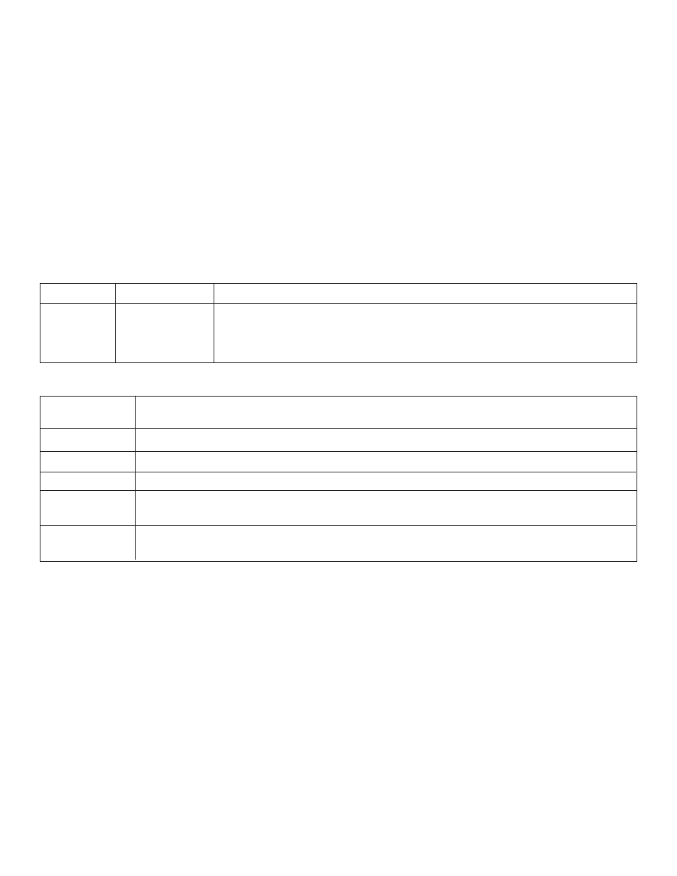
Terminal Identification:
Terminal
Function/Description
Legend
XFMR INPUT
Low voltage AC input.
+ DC OUT ---
Continuous positive (+) DC power output voltage. Common negative (-) output (ground).
+ BAT ---
Stand-by battery connections.
AC FAIL
Used to notify loss of AC e.g connect audible device or alarm panel. Relay is normally energized
N.O., C, N.C.
when AC power is present. Contact rating 1 amp @ 28VDC.
LOW BAT
Used to notify low battery condition e.g connect audible device or alarm panel. Relay is normally
N.O., C, N.C.
energized. Contact rating 1 amp @ 28VDC.
2
Altronix is not responsible for any typographical errors.