Altronix AL1042ULADA Installation Instructions User Manual
Page 6
- 6 -
AL1042ULADA
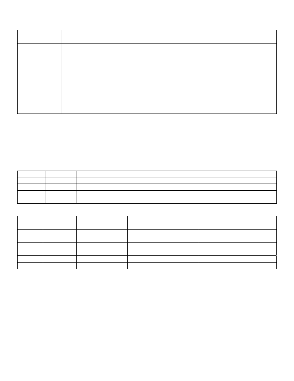
Terminal Identification Table:
Power Supply Board
Terminal Legend Function/Description
L, N
Connect 120VAC to these terminals: L to Hot, N to Neutral.
- DC +
24VDC @ 10 amp continuous, 10 amp in alarm non power-limited output.
AC FAIL
NO, C, NC
Form “C” dry contacts indicate the loss of AC, with AC present terminals marked [NO and C]
are open, [NC and C] are closed. When loss of AC occurs terminals marked [NO and C]
are closed, [NC and C] are open.
AC LOCAL
NC, NO, C
Form “C” dry contacts used to instantaneously signal the loss AC to local annunciation devices,
with AC present terminals marked [NO and C] are open, [NC and C] are closed. When loss of
AC occurs terminals marked [NO and C] are closed, [NC and C] are open.
BAT FAIL
NO, C, NC
Form “C” dry contacts indicate low battery voltage or loss of battery voltage. Under normal
conditions terminals marked [N.O. and C] are open, [NC and C] are closed. During a trouble
condition terminals marked [N.O. and C] are closed, and [N.C. and C] are open (Fig. 3, pg. 8).
+ BAT -
Stand-by battery input (leads provided) (Fig. 3, pg. 8).
*Power Board Parameter Specifications:
• AC Fail condition will report approximately 1.5 hours after loss of AC. To set AC Delay to 30 seconds, power the unit
down (AC supply and Battery) prior to changing switch position. Open or close “AC Delay” switch, respectively.
• Low battery condition will report at approximately 20VDC.
• Battery presence detection will report within 180 seconds after battery remains undetected (missing or removed).
A restored battery will report within 30 seconds.
LED Diagnostics:
Power Supply Board
Red (DC)
Green (AC) Power Supply Status
ON
ON
Normal operating condition.
ON
OFF
Loss of AC, Stand-by battery supplying power.
OFF
ON
No DC output.
OFF
OFF
Loss of AC. Discharged or no stand-by battery. No DC output.
AL842LGK - Logic Board
LED
OFF
ON
BLINK (LONG)*
BLINK (SHORT)**
ON
Normal
Alarm Condition
Trouble Condition
Trouble Condition Memory
ON
Normal
Alarm Condition
Trouble Condition
Trouble Condition Memory
OFF
Normal
Alarm Condition
Trouble Condition
Trouble Condition Memory
OFF
Normal
Alarm Condition
Trouble Condition
Trouble Condition Memory
Input 1
Normal
Alarm Condition
Trouble Condition
---
Input 2
Normal
Alarm Condition
Trouble Condition
---
Fault
Normal
Alarm Condition
---
---
* Indicates existing trouble condition. When a trouble condition (open, short or ground) occurs on a specific output, the
corresponding red output LED, [OUT1-OUT4] will blink. The corresponding green input LED will blink as well.
** Indicates trouble condition memory. When a trouble condition restores, the units red output LEDs, [OUT1-OUT4]
will blink with a shorter and distinctly different duration. The green input LEDs will be off (normal condition).
To reset the memory depress the reset button located on the AL842LGK logic board (Fig. 2c, pg. 8).
The LED(s) will extinguish.
Note: When indicating circuits have restored, trouble memory reset is not required for normal operation.