Maintenance – Altronix AL400ULXJG Installation Instructions User Manual
Page 3
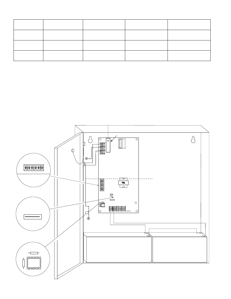
AL400ULXJ
- 3 -
--- DC
+
L
G
N
PTC3
NC C NO NC C NO
+
BAT ---
DC
24V - OPEN
12V - CLOSED
AC
FA
IL
BA
T F
AI
L
SW1
Fuse
Door
CAUTION: De-energize unit prior to servicing. For continued protection
against risk of electric shock and fire hazard replace fuse with the same type
and rating 3.5A, 250V. Replace fuse cover before energizing.
Do not expose to rain or moisture.
Green
Lead
Battery connection (non power-limited)
Wire
Strap
(from
Enclosure
to Door)
115VAC
power mains
non power-
limited
Battery & AC Supervision
Circuit
(power-limited)
Class 1
Fuse Cover
24V - OPEN
12V - CLOSED
SW1
power-limited
NC C NO NC C NO AC FAIL
BAT FAIL
Green
Lead
CAUTION: When power supply board is set for 12VDC use only one (1) 12VDC
stand-by battery.
Keep power-limited wiring separate from non-power limited. Use minimum .25" spacing.
12VDC Rechargeable Battery
(optional)
12VDC Rechargeable Battery
(optional)
AC Delay
AC Delay
Fig. 1
Fig. 1a
Fig. 1b
Fig. 1c
Stand-by Specifications (total current shown):
Output
4hr. of Stand-by &
5 Minutes of Alarm
4hr. of Stand-by &
15 Minutes of Alarm
24hr. of Stand-by &
5 Minutes of Alarm
60hr. of Stand-by &
5 Minutes of Alarm
12VDC/40AH
Battery
Stand-by = 4.0 amp
Alarm = 4.0 amp
Stand-by = 4.0 amp
Alarm = 4.0 amp
Stand-by = 1.0 amp
Alarm = 4.0 amp
Stand-by = 300mA
Alarm = 4.0 amp
24VDC/12AH
Battery
-----------
-----------
Stand-by = 200mA
Alarm = 3.0 amp
-----------
24VDC/40AH
Battery
Stand-by = 3.0 amp
Alarm = 3.0 amp
Stand-by = 3.0 amp
Alarm = 3.0 amp
Stand-by = 1.0 amp
Alarm = 3.0 amp
Stand-by = 300mA
Alarm = 3.0 amp
Maintenance:
Unit should be tested at least once a year for the proper operation as follows:
Output Voltage Test: Under normal load conditions, the DC output voltage should be checked for proper voltage level
(Power Supply Output Specification Chart, pg. 2).
Battery Test: Under normal load conditions check that the battery is fully charged, check specified voltage both at
battery terminal and at the board terminals marked [+ BAT -] to insure there is no break in the battery connection wires.
Note: Maximum charging current under discharges is 0.7 amp.
Note: Expected battery life is 5 years, however it is recommended changing batteries in 4 years or less if needed.