Non-supervised), Wire smoke detector, Hookup diagram – Altronix AL602ULADA Installation Instructions User Manual
Page 7: Fig. 2b fig. 2a
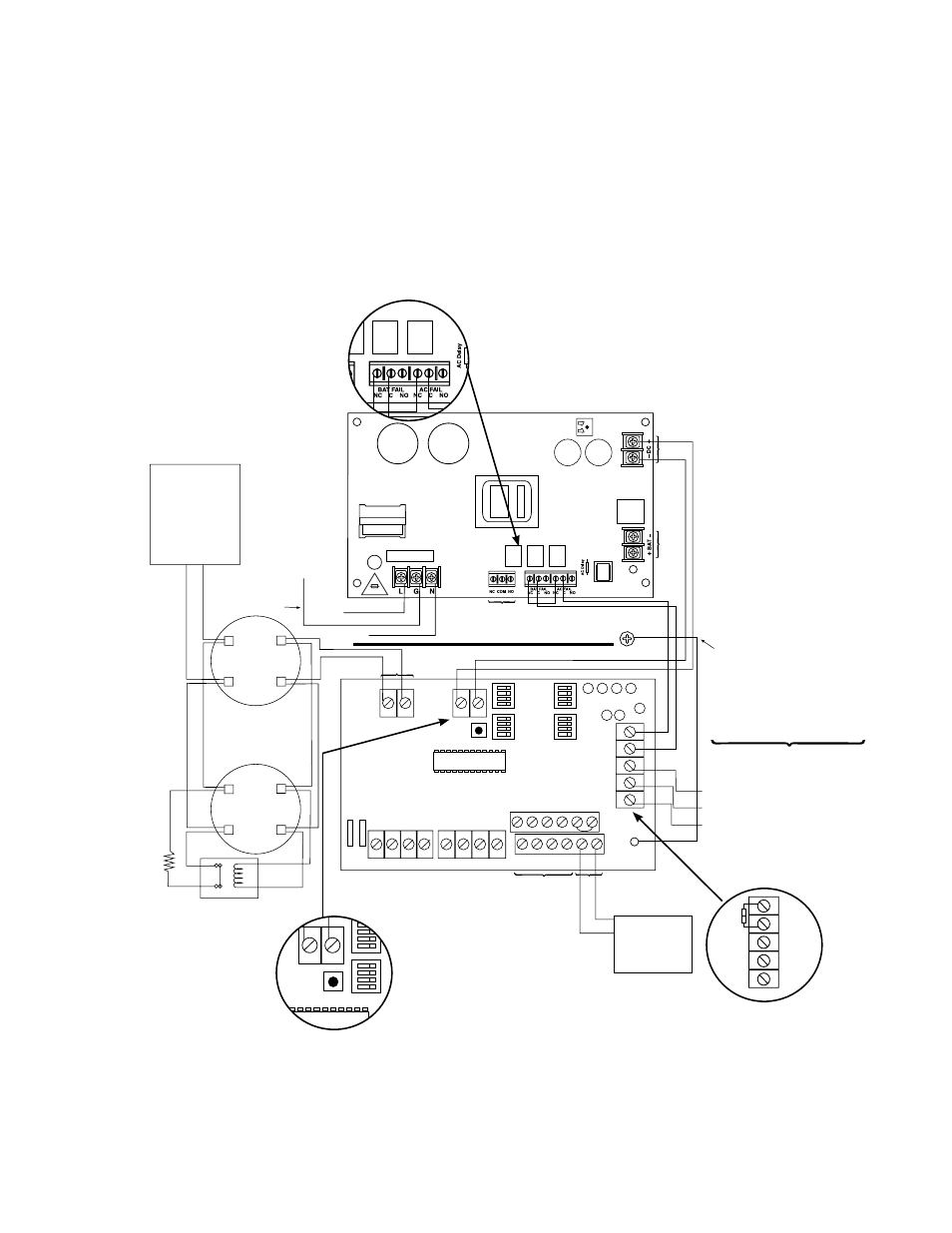
AL602ULADA
- 7 -
This connection is used to
monitor AC and Bat Fail and
will cause a simultaneous trouble
condition to the FACP's IN1 and IN2
Common trouble output to
Digital Communicator or
Local Annunciator Dry output Contact
(Form "C" contacts) (Non-Supervised)
4-wire Smoke
Detector
+
--
+
--
4-wire Smoke
Detector
Fire
Alarm
Control
Panel
(FACP)
EOL Power
Supervision Relay
(Not Supplied)
EOL
Resistor
from
FACP
SW1
-- DC +
SW2
+ OUT1 --
OUT1 OUT2 OUT3 OUT4
INP1 INP2
FAULT
NC
CN
OC
"F
AUL
T" NC
OUT1
OUT3
OUT2
OUT4
INPUT SELECT
TEMPORAL
STROBE SYNC
IN > OUT SYNC
IN1+ IN1--
IN2--
IN2+
C "DRY1" NC
RET1+RET1--
RET2--
RET2+
C "DRY2" NC
+ OUT2 --
+ OUT3 --
+ OUT4 --
INPUT SELECT
TEMPORAL
STROBE SYNC
IN > OUT SYNC
-- AUX +
UPPER TERMINALS
LOWER TERMINALS
Addressable
Control Module
Trigger Output
See Note 2
line
ground
neutral
Green Lead
Green Lead
AC Local
Divider
Use separate knockout. Keep 1/4" spacing from
non power limited wiring
Regulated Power-Limited Outputs
2.5 amp max. per
output in alarm
(total= 6.5 amp)
(Supervised)
Supervised Non-Supervised
Non-Supervised
Non-Supervised
RESET
unswitched 120VAC
power mains
(non-power limited)
Non-po
w
er limite
d
Super
vised
Non-po
w
er limited
5A
250V
Fig. 2
This connection is used to
monitor AC and Bat Fail and
will cause a simultaneous trouble
condition to the FACP's IN1 and IN2
Common trouble output to
Digital Communicator or
Local Annunciator Dry output Contact
(Form "C" contacts) (
Non-Supervised)
4-wire Smoke
Detector
+
--
+
--
4-wire Smoke
Detector
Fire
Alarm
Control
Panel
(FACP)
EOL Power
Supervision Relay
(Not Supplied)
EOL
Resistor
from
FACP
SW1
-- DC +
SW2
+ OUT1 --
OUT1 OUT2 OUT3 OUT4
INP1 INP2
FAULT
NC
CN
OC
"F
AUL
T" NC
OUT1
OUT3
OUT2
OUT4
INPUT SELECT
TEMPORAL
STROBE SYNC
IN > OUT SYNC
IN1+ IN1--
IN2--
IN2+
C "DRY1" NC
RET1+RET1--
RET2--
RET2+
C "DRY2" NC
+ OUT2 --
+ OUT3 --
+ OUT4 --
INPUT SELECT
TEMPORAL
STROBE SYNC
IN > OUT SYNC
-- AUX +
UPPER TERMINALS
LOWER TERMINALS
Addressable
Control Module
Trigger Output
See Note 2
line
ground
neutral
Green Lead
Green Lead
AC Local
Divider
Use separate knockout. Keep 1/4" spacing from
non power limited wiring
Regulated Power-Limited Outputs
2.5 amp max. per
output in alarm
(total= 6.5 amp)
(Supervised)
Supervised Non-Supervised
Non-Supervised
Non-Supervised
RESET
unswitched 120VAC
power mains
(non-power limited)
Non-po
w
er limite
d
Super
vised
Non-po
w
er limited
5A
250V
NC
CN
OC
"F
AUL
T" NC
Fig. 2b
Fig. 2a
These circuits are used to
monitor AC and Bat Fail and
will cause a simultaneous trouble
condition to the FACP's IN1 and IN2
Digital Communicator or
Local Annunciator Dry output Contact
(Form "C" contacts)
4-wire Smoke
Detector
+
--
+
--
4-wire Smoke
Detector
Fire
Alarm
Control
Panel
(FACP)
EOL Power
Supervision Relay
(Not Supplied)
EOL
Resistor
from
FACP
SW1
-- DC +
SW2
+ OUT1 --
OUT1 OUT2 OUT3 OUT4
INP1 INP2
FAULT
NC
CN
OC
"F
AUL
T" NC
OUT1
OUT3
OUT2
OUT4
INPUT SELECT
TEMPORAL
STROBE SYNC
IN > OUT SYNC
IN1+ IN1--
IN2--
IN2+
C "DRY1" NC
RET1+RET1--
RET2--
RET2+
C "DRY2" NC
+ OUT2 --
+ OUT3 --
+ OUT4 --
INPUT SELECT
TEMPORAL
STROBE SYNC
IN > OUT SYNC
-- AUX +
UPPER TERMINALS
LOWER TERMINALS
Addressable
Control Module
Trigger Output
See Note 2
+ DC ---
BAT FAIL
NO C NC NO C NC
+ BAT ---
DC
AC FAIL
L G N
AC
Fuse
Cover
15A
250V
10A
250V
line
ground
neutral
unswitched 120VAC
power mains
(non-power limited)
Green Lead
Use separate knockout.
Keep 1/4" spacing from
non power limited wiring
Power Limited Outputs
2.5 amp per
output in alarm
(total=10 amp)
RESET
J2
Fig. 2c
Trouble Memory
Reset Button
Common trouble
Input/Output
* Indicates current trouble condition. When trouble (open, short or ground) occurs on a specific output, the
corresponding red output LED, [OUT1-OUT4] will blink. The corresponding green input LED will
blink as well. Loop trouble will report within 30 seconds.
** Indicates trouble condition memory. When a trouble condition restores, the units red output LED, [OUT1-OUT4]
will blink with a shorter and distinctly a different duration. The green input LEDs will be off (normal condition).
To reset the memory depress the reset button (Fig. 2c, pg. 7). The LED(s) will extinguish.
Note: If indicating circuits have been restored, memory reset is not required for normal operation of the unit.
Hookup Diagram: