Wiring, Maintenance, Fig. 1 – Altronix AL400UL Installation Instructions User Manual
Page 2: Xfmr
- 2 -
AL400UL
Keep power-limited wiring separate from non power-limited wiring (115VAC / 60Hz Input, Battery Wires).
Minimum 0.25” spacing must be provided.
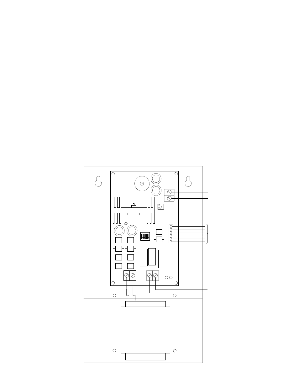
4. Connect devices to be powered to the terminals marked [- DC +] (Fig. 1).
5. Measure output voltage before connecting devices. This helps avoiding potential damage.
6. For Access Control applications batteries are optional. When batteries are not used, a loss of AC will result in
the loss of output voltage. When the use of stand-by batteries is desired, they must be lead acid or gel type.
Connect battery to the terminals marked [ -- BAT + ] (Fig. 1). Use two (2) 12VDC batteries connected in
series for 24VDC operation (battery leads included).
7. Connect appropriate signaling notification devices to AC FAIL & BAT FAIL (Fig. 1) supervisory relay outputs.
Wiring:
Use 18 AWG or larger for all power connections.
Note: Take care to keep power-limited circuits separate from non power-limited wiring (115VAC, Battery)
Maintenance:
Unit should be tested at least once a year for the proper operation as follows:
Output Voltage Test: Under normal load conditions the DC output voltage should be checked for proper voltage level
(see Power Supply Voltage Output Specifications Chart).
Battery Test: Under normal load conditions check that the battery is fully charged, check specified voltage both at
the battery terminal and at the board terminals marked [ -- BAT + ] to ensure that there is no break in the battery
connection wires.
Note: Maximum charging current under discharges is 1.2 amp.
Note: Expected battery life is 5 years; however, it is recommended changing batteries in 4 years or less if needed.
--
DC
+
LOW BA
T NO C NC C NO NC AC F
AIL
-- BAT +
DC
AC
1
2
3
4
ON
AC AC
24V - SW1, 2 OFF
SW3, 4 ON
12V - SW1, 2 ON
SW3, 4 OFF
XFMR
DC output
to devices
(power-limited)
Battery and AC
Supervision Circuit
(power-limited)
Battery connection
(non power-limited)
Switch Position:
24VDC = SW1, 2 OFF
SW3, 4 ON
12VDC = SW1 CLOSED
SW3, 4 OFF
Fig. 1