Xfmr, Maintenance, Fig. 1 – Altronix AL600ULXD Installation Instructions User Manual
Page 2: Fig. 2 - 115vac input, 230vac input
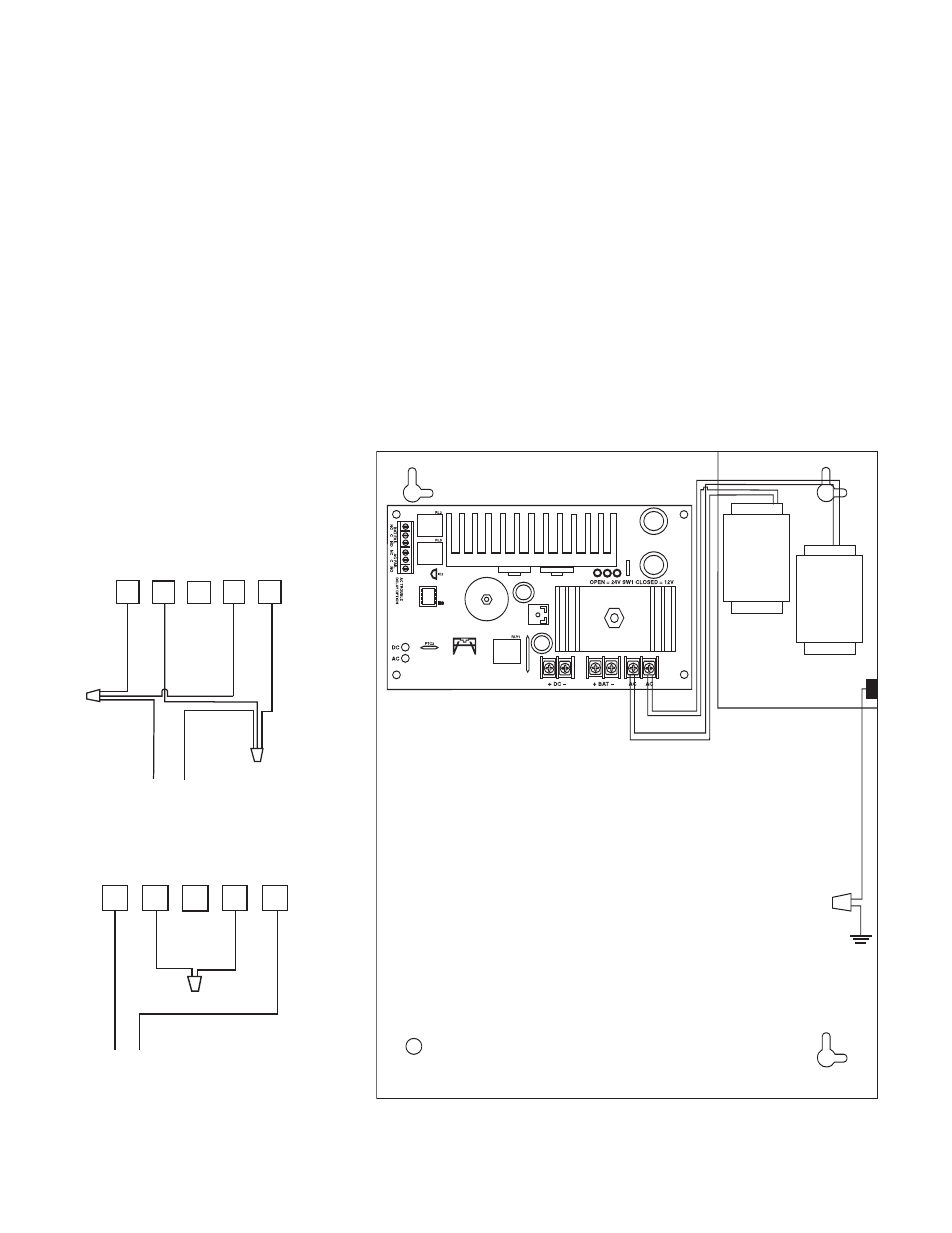
3. Measure output voltage before connecting devices. This helps avoid potential damage.
4. Connect devices to be powered to terminals marked [- DC +] (Fig. 1).
5. For Access Control applications, batteries are optional. When batteries are not used a loss of AC will result in the
loss of output voltage. When the use of stand-by batteries is desired, they must be lead acid or gel type.
Connect battery to terminals marked [+ BAT -] (Fig. 1) (battery leads included). Use two (2)
12VDC batteries connected in series for 24VDC operation.
6. Connect appropriate trouble reporting devices to AC Fail & Low battery (Fig. 1) supervisory
relay outputs marked [N.C., C, N.O.]. Use 22 AWG to 18 AWG for AC Fail / Low Battery reporting. AC Failure
will report in 5 minutes. For a 6 hour delay on reporting cut resistor R1(Fig. 1).
Maintenance:
Unit should be tested at least once a year for the proper operation as follows:
Output Voltage Test: Under normal load conditions, the DC output voltage should be checked for proper voltage level
(Power Supply Voltage Output Specifications Chart).
Battery Test: Under normal load conditions check that the battery is fully charged, check specified voltage both
at battery terminal and at the board terminals marked [- BAT +] to insure there is no break in the battery
connection wires.
Note: Maximum charging current under discharges is .7 amp.
Note: Expected battery life is 5 years, however it is recommended changing batteries in 4 years or less if needed.
115VAC input
50/60 Hz, 1.9 amp
230VAC input
50/60 Hz, .95 amp
Green
Lead
(ground)
XFMR
XFMR
Fig. 1
Altronix is not responsible for any typographical errors. Product specifications are subject to change without notice.
Fig. 2 - 115VAC Input
5
4
3
2
1
B
L
A
C
K
Y
E
L
L
O
W
B
L
U
E
W
H
IT
E
L
IN
E
N
E
U
T
R
A
L
115VAC Input
115VAC Input
Fig. 3 - 230VAC Input
5
4
3
2
1
B
L
A
C
K
Y
E
L
L
O
W
B
L
U
E
W
H
IT
E
230VAC Input
230VAC Input