Altronix VertiLine8CD Installation Instructions User Manual
Page 4
- 4 -
Vertiline8C
A
C
P
O
W
ER
1
2
3
4
5
6
7
8
28
VA
C
O
FF
24
VA
C
M
ai
n
Fu
se
1-
8
1
2
3
4
5
6
7
8
1
2
3
4
5
6
7
8
N
P
N
P
N
P
N
P
N
P
N
P
N
P
N
P
O
F
F
R
E
S
E
T
A
C
P
O
W
ER
M
ai
n
Fu
se
1-
8
N
P
N
P
N
P
N
P
N
P
N
P
N
P
N
P
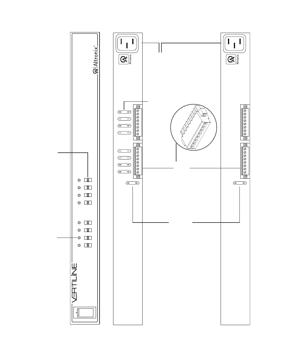
1b
- Output v
olta
g
e switc
hes:
Selects
24V
A
C or 28V
A
C
or OFF for each output.
1c
- Main Fuse:
Protects
the
transfor
mer
ag
ainst o
v
erload.
1a
- LED(s) 1-8:
P
o
w
er
LED indicators.
1f
- IEC 320
Connector:
115V
A
C
60Hz
(g
rounded line
cord included).
F
ig
. 1
1d
- P
o
w
er
Outputs:
24V
A
C
or
28V
A
C.
1e
- Output Fuses:
Automoti
v
e
b
lade
fuses.
V
er
tiline8C,
V
er
tiline8CD,
V
er
tiline83C
or
V
er
tiline83CD (fr
ont)
V
er
tiline8C or
V
er
tiline83C (r
ear)
V
er
tiline8CD or
V
er
tiline83CD (r
ear)
V
ertiline8CD
and
V
ertiline83CD do not have output fuses on the r
ear of the r
ac
k mount
chassis.
The output PTCs ar
e located on the inside of the r
ac
k mount c
hassis.
See also other documents in the category Altronix Accessories for electrical:
- NetWay3012 Installation Instructions (2 pages)
- HubWay 16Di Data Sheet (2 pages)
- Maximal77 Installation Instructions (20 pages)
- HubWay Dvi Data Sheet (1 page)
- HubWay Av2 Data Sheet (1 page)
- PD4CB Installation Instructions (1 page)
- ACM4CB Data Sheet (2 pages)
- VertiLine63D Data Sheet (2 pages)
- eBridge16CR Installation Instructions (8 pages)
- LPS3WP12 Data Sheet (2 pages)
- VertiLine246D Data Sheet (2 pages)
- T24130D Data Sheet (1 page)
- eBridge1PCRTX Data Sheet (2 pages)
- RB5 Installation Instructions (1 page)
- Tempo2 Data Sheet (1 page)
- BC600G Data Sheet (1 page)
- eBridge1CRT Data Sheet (2 pages)
- AL400ULB Data Sheet (1 page)
- PT2724 Installation Instructions (8 pages)
- OLS180 Installation Instructions (2 pages)
- HubWay 8CD Data Sheet (2 pages)
- AL175ULB Data Sheet (1 page)
- StrikeIt2 Installation Instructions (8 pages)
- LPD Data Sheet (1 page)
- eBridge4SK Installation Instructions (8 pages)
- LPS3AC Installation Instructions (2 pages)
- T2428100 Data Sheet (1 page)
- TP1650 Data Sheet (1 page)
- T2885D Data Sheet (1 page)
- T2428175 Installation Instructions (1 page)
- T1656 Installation Instructions (1 page)
- SMP3 Data Sheet (1 page)
- RBR1224 Data Sheet (1 page)
- HubWay LD16D Data Sheet (2 pages)
- eFlow102NX16D Installation Instructions (16 pages)
- T24175C Data Sheet (1 page)
- Maximal5D Data Sheet (2 pages)
- Maximal7 Installation Instructions (16 pages)
- HubWay 8CDS Data Sheet (2 pages)
- eFlow4NX8D Installation Instructions (16 pages)
- MOM5C Data Sheet (1 page)
- eBridge16PCRX Installation Instructions (8 pages)
- HubWay EX16SP Data Sheet (2 pages)
- T24130C Installation Instructions (1 page)
- Maximal5 Data Sheet (2 pages)