Altronix SMP3PMP8CB Installation Instructions User Manual
Smp3ctx series - installation guide
SMP3CTXseries
- 1 -
Power Supply Voltage Output Specifications: *
Output VDC
Switch Position
Max. Load DC
12VDC
SW1 - Closed (Fig. 1b, pg. 3)
2.5 amp
24VDC
SW1 - Open (Fig. 1b, pg. 3)
2.5 amp
*Specified at 25˚ C ambient.
Installation Instructions:
Wiring methods shall be in accordance with the National Electrical Code/NFPA 70/NFPA 72/ANSI, and with all local
codes and authorities having jurisdiction. Product is intended for indoor use only.
1. Mount unit in desired location. Mark and predrill holes in the wall to line up with the top two keyholes in the
enclosure. Install two upper fasteners and screws in the wall with the screw heads protruding. Place the enclosure’s
upper keyholes over the two upper screws, level and secure. Mark the position of the lower two holes. Remove the
enclosure. Drill the lower holes and install the three fasteners. Place the enclosure’s upper keyholes over the two
upper screws. Install the two lower screws and make sure to tighten all screws (Enclosure Dimensions, pg. 4).
Secure enclosure to earth ground.
2. Set SW1 on the power supply board to the desired DC output voltage
(Power Supply Voltage Output Specification Chart).
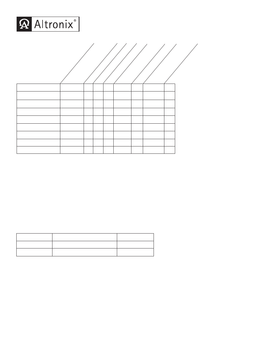
SMP3CTX Series Power Supply Configuration Reference Chart:
Overview:
These units will convert a 115VAC or 230VAC, 50/60Hz input, into a regulated 12VDC or 24VDC output up 2.5 amp of
continuous load current (see specifications).
Specifications:
• Universal 115/230VAC input.
• Maximum charge current .5 amp.
• Filtered and electronically regulated outputs.
• Built-in charger for sealed lead acid or gel type batteries.
• Automatic switch over to stand-by battery when
AC fails (zero voltage drop).
• AC input and DC output LED indicators.
• Short circuit and thermal overload protection.
• Complete with power supply, power distribution module
(when applicable), enclosure, cam lock & battery leads.
• Power on-off switch.
Supervised models only:
• AC fail supervision (form "C" contacts).
• Low battery supervision (form "C" contacts).
SMP3CTX Series - Installation Guide
SMP3CTX
-
1
-
-
-
-
.65 / .35 2.5
SMP3PMCTX
-
1
-
-
-
x
.65 / .35 2.5
SMP3PMCTXX
-
1
-
-
-
x
.65 / .35 2.5
SMP3PMP4
PD4
4
x
-
3.5
x
.65 / .35 2.5
SMP3PMP4CB
PD4CB
4
-
x
2.5
x
.65 / .35 2.5
SMP3PMP8
PD8
8
x
-
3.5
x
.65 / .35 2.5
SMP3PMP8CB
PD8CB
8
-
x
2.5
x
.65 / .35 2.5
SMP3PMP16
PD16W
16
x
-
3.5
x
.65 / .35 2.5
SMP3PMP16CB
PD16WCB 16
-
x
2.5
x
.65 / .35 2.5
A
ltr
on
ix
M
od
el
N
um
be
r
A
cc
es
so
ry
Po
w
er
D
is
tr
ib
ut
io
n
M
od
ul
e(
s)
N
um
be
r
of
O
ut
pu
ts
Fu
se
d
O
ut
pu
ts
PT
C
O
ut
pu
ts
In
di
vi
du
al
O
ut
pu
t
R
at
in
g
(a
m
p)
11
5V
A
C
/
23
0V
A
C
In
pu
t
C
ur
re
nt
(a
m
p)
12
/2
4V
D
C
To
ta
l
O
ut
pu
t
C
ur
re
nt
(a
m
p)
Su
pe
rv
is
ed