Front rear – Altronix HubWay EX16S Installation Instructions User Manual
Page 4
- 4 -
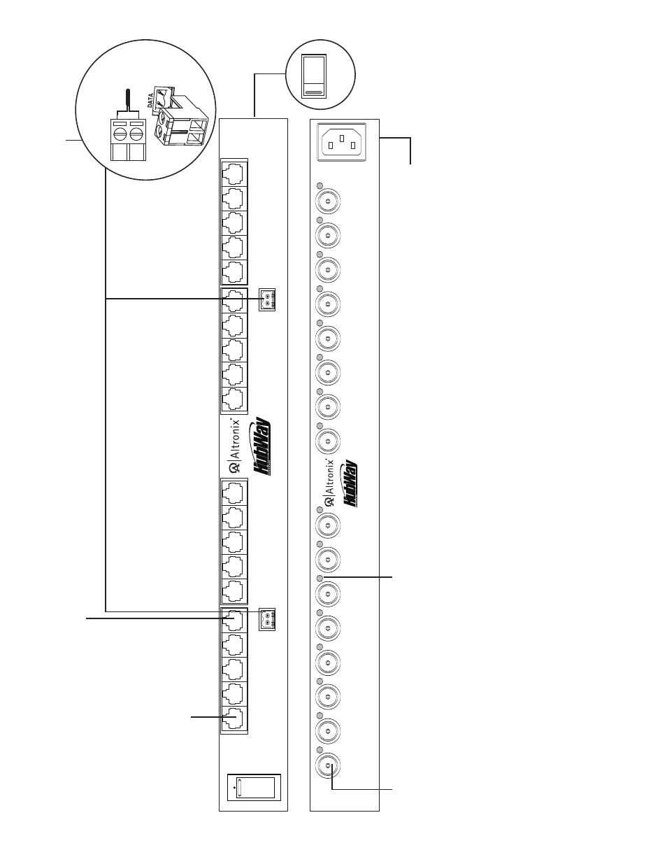
HubWayEX16S Active Hub Unit
3g
- Input
V
olta
g
e
Switc
h:
Selects
115V
A
C
/230V
A
C
(s
witch
is
located on the
left side of
the unit).
1
2
3
4
CH
1-
4
CH
5-
8
DA
TA 1-8
DA
TA
9-
16
5
6
7
8
9
10
11
12
CH
9-
12
13
14
15
16
CH
13
-1
6
AC
P
OW
ER
16
15
14
13
12
11
10
9
8
7
6
5
4
3
2
1
O
F
F
R
E
S
E
T
1
2
3
4
CH
1-
4
CH
5-
8
DA
TA 1-8
5
6
7
8
AC
P
OW
ER
8
7
6
5
4
3
2
1
O
F
F
R
E
S
E
T
3a
- Channels 1-16:
CA
T
-5
or
higher str
uctured cab
le to
V
ideo/Balun Combiners at
cameras 1-8 or 1-16.
When using
an optional HubSat4D an
y of the
outputs can be utilized for the data
transmission to PTZ’
s.
3d
- BNC Connector:
V
ideo
outputs to head end
equipment (D
VR).
3b
- Channels 1-4,
Channels 5-8,
Channels 9-12 & Channels 13-16:
CA
T
-5
or higher str
uctured cab
le from optional HubSat4D/4Di
enab
les video transmission from up to four (4) cameras.
3e
- LED(s) 1-16:
V
ideo
signal indicators.
3f
- IEC 320 Connector:
Grounded
line
cord included.
F
ig
. 1
3c
- Data:
Remo
v
ab
le
ter
minal b
locks for RS422/RS485
input from head end equipment (D
VR) for PTZ control.
+ --
D
a
ta
i
n
p
u
t
fr
o
m
H
e
a
d
E
n
d
E
q
u
ip
m
e
n
t
(D
V
R
).
T
o
p
V
ie
w
1
1
5
V
A
C
2
2
0
V
A
C
F
ront
Rear
- NetWay3012 Installation Instructions (2 pages)
- HubWay 16Di Data Sheet (2 pages)
- Maximal77 Installation Instructions (20 pages)
- HubWay Dvi Data Sheet (1 page)
- HubWay Av2 Data Sheet (1 page)
- PD4CB Installation Instructions (1 page)
- ACM4CB Data Sheet (2 pages)
- VertiLine63D Data Sheet (2 pages)
- eBridge16CR Installation Instructions (8 pages)
- LPS3WP12 Data Sheet (2 pages)
- VertiLine246D Data Sheet (2 pages)
- T24130D Data Sheet (1 page)
- eBridge1PCRTX Data Sheet (2 pages)
- RB5 Installation Instructions (1 page)
- Tempo2 Data Sheet (1 page)
- BC600G Data Sheet (1 page)
- eBridge1CRT Data Sheet (2 pages)
- AL400ULB Data Sheet (1 page)
- PT2724 Installation Instructions (8 pages)
- OLS180 Installation Instructions (2 pages)
- HubWay 8CD Data Sheet (2 pages)
- AL175ULB Data Sheet (1 page)
- StrikeIt2 Installation Instructions (8 pages)
- LPD Data Sheet (1 page)
- eBridge4SK Installation Instructions (8 pages)
- LPS3AC Installation Instructions (2 pages)
- T2428100 Data Sheet (1 page)
- TP1650 Data Sheet (1 page)
- T2885D Data Sheet (1 page)
- T2428175 Installation Instructions (1 page)
- T1656 Installation Instructions (1 page)
- SMP3 Data Sheet (1 page)
- RBR1224 Data Sheet (1 page)
- HubWay LD16D Data Sheet (2 pages)
- eFlow102NX16D Installation Instructions (16 pages)
- T24175C Data Sheet (1 page)
- Maximal5D Data Sheet (2 pages)
- Maximal7 Installation Instructions (16 pages)
- HubWay 8CDS Data Sheet (2 pages)
- eFlow4NX8D Installation Instructions (16 pages)
- MOM5C Data Sheet (1 page)
- eBridge16PCRX Installation Instructions (8 pages)
- HubWay EX16SP Data Sheet (2 pages)
- T24130C Installation Instructions (1 page)
- Maximal5 Data Sheet (2 pages)