Altronix HubSat 4D Installation Instructions User Manual
Page 4
- 4 -
HubSat4D
6. Data connection between HubSat4D and HubWay/HubWayLD/HubWayLDH UTP Transceiver Hubs:
Plug the RJ45 connector at one end of a structured cable into the RJ45 jack marked [Data 1-4] of the HubSat4D
(Fig. 1h, pg. 4).
Plug the RJ45 connector at the opposite end of the structured cable into the corresponding RJ45 channel jack
of the HubWay/HubWayLD/HubWayLDH UTP Transceiver Hubs (Fig. 6, pg. 7).
When using fixed cameras disregard this step.
Example: Using RJ45 jack marked [Video 1-4] of HubSat4D connected to [Channels 1-4] of the
HubWay/HubWayLD/HubWayLDH for video transmission, Using the RJ45 jack marked [Data 1-4] of HubSat4D
connected to the Channel jack marked [4] of the HubWay/HubWayLD/HubWayLDH.
Note: Channels 1-3 can not be used for video transmission when using the RJ45 jack marked [CH 1-4] of the
HubWay/HubWayLD/HubWayLDH.
The output voltage switches 1-4 must be set to OFF position (Fig. 6, pg. 7).
7. Connect Video Balun/Combiner at camera 1 to the HubSat4D unit utilizing CAT-5 or higher structured cable.
Plug the RJ45 connector at one end of a structured cable into the RJ45 jack marked [PVD1] of the
HubSat4D (Fig. 1e, pg. 4). Plug the RJ45 connector at the opposite end of the structured cable into the
RJ45 jack of the Video Balun/Combiner located at camera 1.
• For 24VAC cameras use Altronix model HubWayAv Video Balun/Combiner (Figs. 2a, 2b, pg. 6).
• For 12VDC cameras use Altronix model HubWayDv Video Balun/Combiner (Figs. 2c, 2d, pg. 6).
AC LED (Green) of the HubWayAv or DC LED (Red) of the HubWayDv Video Balun/Combiners will illuminate
indicating power is present at the cameras (Fig. 2b, 2d, pg. 6).
Repeat this step for each additional camera [OUT2-4].
Note: The combined total cable distance for video transmission must not exceed the following distances:
- 750 ft. between the HubWay and each camera routed through the HubSat4D.
- 3000 ft. between the HubWayLD/HubWayLDH and each camera routed through the HubSat4D.
8. Set illuminated master power disconnect circuit breaker to the RESET (ON) position (Fig. 4, pg. 6) and measure the
output voltage at the power output of each Video Balun/Combiner (Figs. 2b, 2d, pg. 6) before powering each camera
to insure proper operation and avoid possible damage.
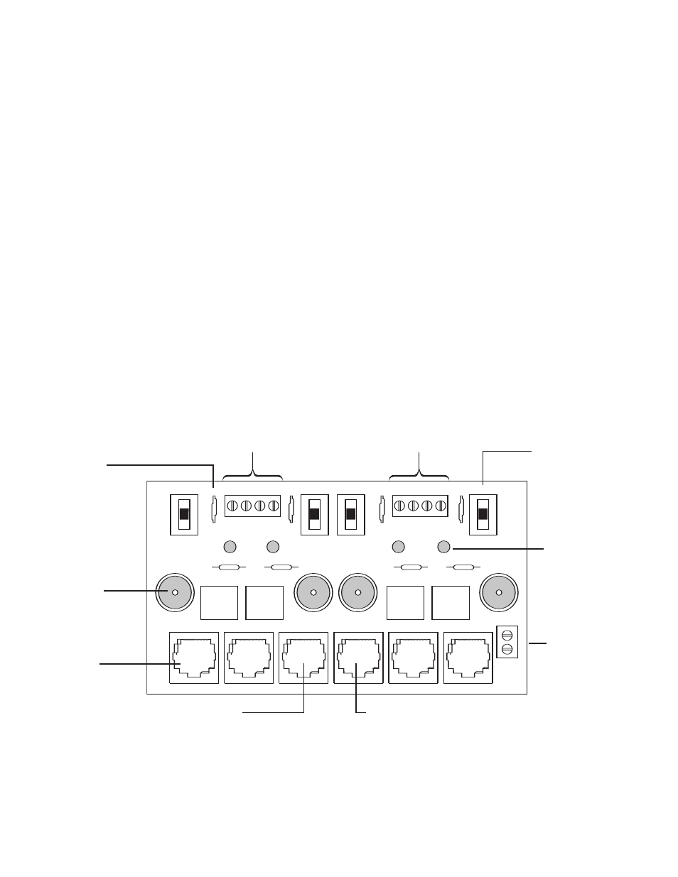
Fig. 1 - HubSat4D Circuit Board
1i - Channels 1-4:
CAT-5 or higher
structured cable
to cameras.
PVD1
VIDEO1
VIDEO2
VIDEO3
VIDEO4
PVD2
PVD3
PVD4
+
D
A
T
A
-
DATA 1-4
VIDEO 1-4
28VAC
24VAC
28VAC
24VAC
28VAC
24VAC
28VAC
24VAC
O
F
F
O
F
F
O
F
F
O
F
F
AUX1
AUX2
AUX3
AUX4
1d - Output
Voltage Switches:
Selects
24VAC/28VAC/OFF
for each output.
1e - LED(s) 1-4:
Power output
indicators.
1a - BNC
Connector: Video
in from remote
camera video
out to DVR.
1g - Channels 1-4: Single CAT-5 or higher
structured cable out to HubWay8/16, HubWayLD8/16,
HubWayLDH8/16 enables transmission
of up to four (4) video signals.
1h - Data: CAT-5 or higher structured
cable to data port on HubWay8/16, HubWayLD8/16,
HubWayLDH8/16 or head end equipment (DVR).
1c - Power Terminals: 24VAC/28VAC power outputs.
1b - Output
PTCs: Protects
each output.
1f - Data:
RS422/RS485
input from head
end equipment
(DVR) for PTZ
control.