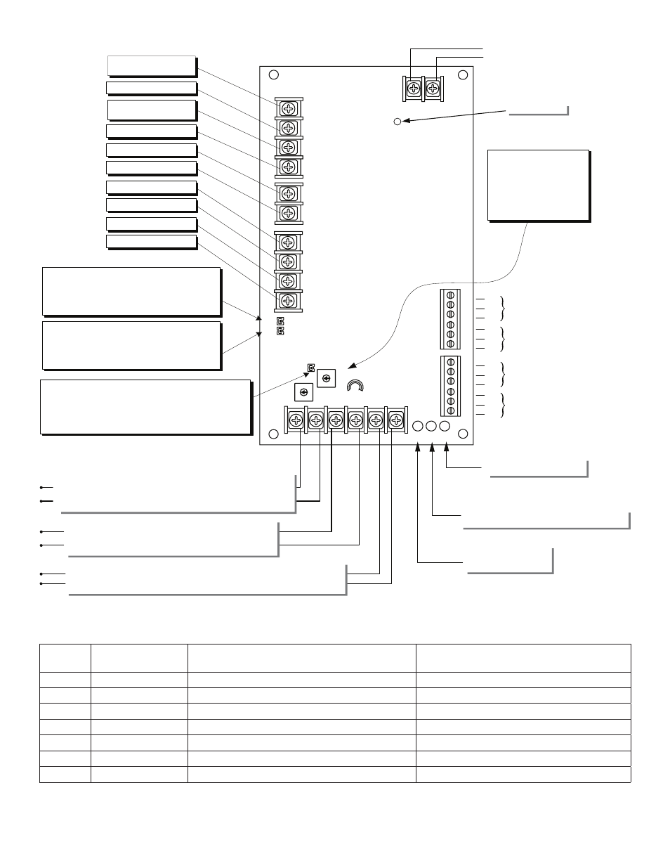
Wiring distance table, Ac input from transformers, Fig. 2 – Altronix StrikeIt1 Installation Instructions User Manual
Page 6: Inrush current wire gauge electric butt or pivot, Out1 and out2
- 6 -
StrikeIt1
+
BA
T
--
--
24VDC
+
+ 12VDC
--
NO
C
NC
NO
C
NC
DELA
YED1
FOLLOWER1
NO
C
NC
NO
C
NC
DELA
YED2
FOLLOWER2
XFMR
AC
FAI
MIN
MAX
INP1 INP2
--
OUT1
+-
- OUT2
+
DLY 1
DLY 2
IN1
GND
IN2
OUT2
TIMER
OUT1
TIMER
GND
GND FACP
FA SELECT
AC Input
from transformers
Note: For independent operation of Output 1 and 2, connect NO dry contact between IN1 and GND and/or IN2 and GND.
For sequential operation of OUT1 and OUT2 install a jumper between IN1 and IN2 and a jumper between both GND terminals.
FA LED
When red LED is lit,
fire alarm circuit is open.
DLY1 Jumper
Intact – ½ second delay after IN1 is shorted before
Delayed 1 Relay is switched for 1 second.
Removed –1 second delay after IN1 is shorted before
Delayed 1 Relay is switched for 1 second.
DLY2 Jumper
Intact – ½ second delay after IN2 is shorted before
Delayed 2 Relay is switched for 1 second.
Removed –1 second delay after IN2 is shorted before
Delayed 2 Relay is switched for 1 second.
FA SELECT Jumper
Fire Alarm Interface Mode
Intact - Fail Safe – Both outputs de-energized and Relay
Follower1 and Follower2 De-energized when FA contacts open.
Removed – Fail Secure – Both outputs energized Relay
Follower1 and Follower2 Energized when FA contacts open.
INP2 LED
Indicator for Input2 with the
same function as INP1 LED.
AC Power LED
Fire Alarm Interface
Connect these terminals to a normally closed dry contact that
opens upon fire alarm activation. With FA SELECT Jumper intact,
outputs # 1 and # 2 will drop power and Follower1and 2 will
de-energize. With FA SELECT Jumper removed, outputs #1 and #2
and Follower1 and 2 will energize upon fire alarm activation.
If FA interface is not used, place jumper between both FA terminals.
12V AUX Output --
12V AUX Output +
12VDC @ 1.0A
24V AUX Output +
Battery 24VDC +
Output 1 24VDC +
Output 1 24VDC --
Output 2 24VDC +
Output 2 24VDC --
24V AUX Output --
24VDC @ 1.0A
NO
C
NC
NO
C
NC
NO
C
NC
NO
C
NC
OUT1 and OUT2
Relock delay adjustment.
Used to hold OUT1 or OUT2
energized after a momentary
closure across IN1 or IN2.
Set for 0 seconds for output
to follow input. Turn
clockwise to increase time.
INP1 LED
When green LED is lit steady, Input 1 is energized.
Blinking Slow LED – Output is open.
Rapid blinking LED – Output is shorted.
Follower 1 - This relay will activate
immediately when OUTPUT 1
is energized.
Delayed 1 - This relay will activate
after .5 sec. or 1 sec. (depending on
the position of DLY1 jumper) when
OUTPUT 1 is energized.
Follower 2 - This relay will activate
immediately when OUTPUT 2
is energized.
Delayed 2 - This relay will activate
after .5 sec. or 1 sec. (depending on
the position of DLY2 jumper) when
OUTPUT 2 is energized.
Input #2
Connect normally open dry contacts from
key switch, timer, remote release or any maintained/
momentary switch. Output #2 energizes while input is closed.
Input #1
Connect normally open dry contacts from key switch, timer, remote release
or any maintained/momentary switch. Output #1 energizes while input is closed.
Battery 24VDC --
Fig. 2
Wiring Distance Table:
InRush
Current
Wire Gauge
Electric Butt or Pivot
Max distance from Power Supply to frame side of opening
EPT
Max distance from Power Supply to frame side of opening
8 amp
14 AWG Stranded
75 ft.
100 ft.
8 amp
12 AWG Stranded
175 ft.
200 ft.
12 amp
14 AWG Stranded
60 ft.
75 ft.
12 amp
12 AWG Stranded
80 ft.
100 ft.
16 amp
14 AWG Stranded
40 ft.
75 ft.
16 amp
12 AWG Stranded
60 ft.
80 ft.
16 amp
10 AWG Stranded
100 ft.
125 ft.