Maintenance, Strikeit1 terminal identification, Request to exit pir jumpers – Altronix StrikeIt1 Installation Instructions User Manual
Page 5
StrikeIt1
- 5 -
Maintenance:
Unit should be tested at least once a year for the proper operation as follows:
FACP Supervision: To insure proper connection and operation of the Fire Alarm disconnect hookup, remove wire from
the terminal marked [FACP] on StrikeIt1. With the [FA Select] jumper removed, locked Panic Hardware Devices will
unlock. With the [FA Select] jumper in place, unlocked Panic Hardware Devices will relock. When the wire is
reconnected to the [FACP] terminal the Panic Hardware Devices will relock with the [FA Select] jumper removed or will
unlock with the [FA Select] jumper in place.
Output Voltage Test: Under normal load conditions the DC output voltage should be checked for proper voltage level.
Battery Test: Under normal load conditions check that the battery is fully charged, check specified voltage both at
battery terminal and at the board terminals marked [+ BAT -- ] to insure there is no break in the battery connection wires.
Note: Maximum charging current under discharge is 300mA.
Note: Expected battery life is 5 years, however it is recommended changing batteries in 4 years or less if needed.
Caution: For continuous protection against risk of electric shock and fire hazard, replace input fuse with the same type
and rating: 3.5 amp/250V. Do not expose to rain or moisture; indoor use only.
StrikeIt1 Terminal Identification:
Terminal Legend
Function/Description
+ 12VDC --
12VDC Auxiliary Output @ 1 amp.
-- 24VDC +
24VDC Auxiliary Output @ 1 amp.
+ BAT --
24VDC Stand-by Battery Connection (Two (2) 12VDC batteries wired in series).
-- OUT 1 +
Connect 24VDC Panic Hardware Device #1.
-- OUT 2 +
Connect 24VDC Panic Hardware Device #2.
FACP / GND
Normally Closed Dry Contact from Fire Alarm Control.
IN1 / GND
N/O Trigger input controls Output 1. May be held closed for extended unlocking.
IN2 / GND
N/O Trigger input controls Output 2. May be held closed for extended unlocking.
Delayed 1
Dry form “C” contacts provide a 1 second momentary pulse after a preset delay. With jumper
[DLY1] in place, the delay is 0.5 seconds. With jumper [DLY1] removed the delay is 1 second. This
permits the Panic Hardware Device to fully unlock before signaling auto operator to swing door.
Delayed 2
Dry form “C” contacts provide a 1 second momentary pulse after a preset delay. With jumper
[DLY2] in place, the delay is 0.5 seconds. With jumper [DLY2] removed the delay is 1 second.This
permits the Panic Hardware Device to fully unlock before signaling auto operator to swing door.
Follower 1
Dry form “C” contact. Energizes while output 1 is energized. Enables outside ADA switch plate
to actuate auto operator while door is unlocked. De-activates outside ADA actuator while door is
locked.
Follower 2
Dry form “C” contact. Energizes while output 2 is energized. Enables outside ADA switch plate
to actuate auto operator while door is unlocked. De-activates outside ADA actuator while door is
locked.
+ BAT --
-- 24VDC +
+ 12VDC --
XFMR
AC
FA
I
MIN
MAX
INP1
INP2
-- OUT1 + -- OUT2 +
DL
Y
1
DL
Y
2
IN1
GND
IN2
GND
GND
FACP
FA
SELECT
Panic Hardware Device
+
---
Fire
Alarm
Control
Panel
Automatic
Door
Operator
Automatic
Door
Operator
Rechargeable
Batteries
Request
to Exit
PIR
Panic Hardware Device
Auxiliary
Device
Auxiliary
24VDC
Device
Auxiliary
Device
12VDC
+
---
12VDC
FA
I
MIN
MAX
INP1
INP2
IN
1
GN
D
IN
2
GN
D
GN
DF
AC
P
Request
to Exit
PIR
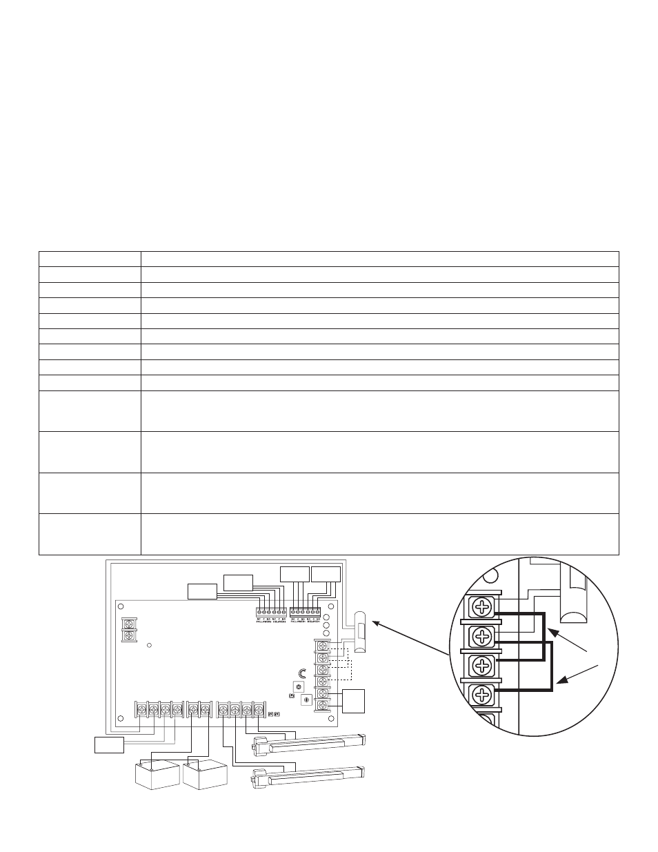
Jumpers
Fig. 1a
Triggering Input 1 and Input 2
from a single actuating device.
Fig. 1