Installation instructions, Fig. 1c – Altronix AL300ULXR Installation Instructions User Manual
Page 3
AL300ULX series
- 3 -
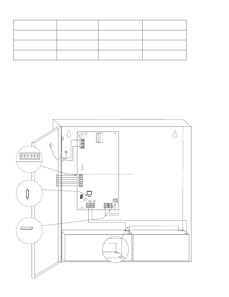
Door
CAUTION: De-energize unit prior to servicing. For continued protection against risk of electric
shock and fire hazard replace fuse with the same type and rating. Do not expose to rain or moisture.
Battery connection (non power limited)
Switch Position:
24VDC = SW1 OPEN
12VDC = SW1 CLOSED
Wire
Strap
(from
Enclosure
to Door)
Battery & AC
Supervision
Circuit
(power limited)
-
For 12VDC Operation
use hook-up in the
inset on the right
CAUTION: When power supply board is set for 12VDC use only one (1) 12VDC stand-by battery.
Keep power limited wiring separate from non-power limited. Use minimum 0.25" spacing.
12VDC Rechargeable Battery
(optional)
12VDC Rechargeable Battery
(optional)
115VAC
power mains
non power-
limited
Green
Lead
Class 1
+
DC ---
+
BAT ---
AC
DC
Ba
t
Risk of Fir
e,
Replace Fuse
s
As Marked
Opened - 24V
Closed - 12V
J1
SW1
Opened - 24V
Closed - 12V
SW1
5A 250
V
15A 250V
AC Delay
15
L
G
N
NC C NO NC C NO
AC Fail
Bat Fail
DC Output to devices
(power limited)
NC C NO NC C NO
Battery &
AC Supervision Circuit
(power limited)
J1
AC Delay
Fig. 1
Fig. 1a
Fig. 1b
Stand-by Specifications (total current shown):
Output
4 hr. of Stand-by &
5 Minutes of Alarm
24 hr. of Stand-by &
5 Minutes of Alarm
60 hr. of Stand-by &
5 Minutes of Alarm
12VDC / 40AH Battery
Stand-by = 2.5 amp
Alarm = 2.5 amp
Stand-by = 1.0 amp
Alarm = 2.5 amp
Stand-by = 300mA
Alarm = 2.5 amp
24VDC / 12AH Battery
--------
Stand-by = 200mA
Alarm = 2.5 amp
--------
24VDC / 40AH Battery
Stand-by = 2.5 amp
Alarm = 2.5 amp
Stand-by = 1.0 amp
Alarm = 2.5 amp
Stand-by = 300mA
Alarm = 2.5 amp
Installation Instructions:
Wiring methods shall be in accordance with the National Electrical Code/NFPA 70/NFPA 72/ANSI, and with all local
codes and authorities having jurisdiction. Product is intended for indoor use only.
1. Mount unit in desired location. Mark and predrill holes in the wall to line up with the top two keyholes in the
enclosure. Install two upper fasteners and screws in the wall with the screw heads protruding. Place the enclosure’s
upper keyholes over the two upper screws, level and secure. Mark the position of the lower two holes. Remove the
enclosure. Drill the lower holes and install the two fasteners. Place the enclosure’s upper keyholes over the two
upper screws. Install the two lower screws and make sure to tighten all screws (Enclosure Dimensions, pgs. 7, 8).
Secure enclosure to earth ground.
Fig. 1c